The selective amplifier is a class of signal amplifiers which works at high or very high frequencies. These amplifiers are applied for amplification of the signals with narrow band around the central frequency fo. These needs comes from the application of these amplifiers in the receiving technique for selecting only the modulated high frequency signal form one transmitting station and not allowing the interferer signals from the near transmitting stations which can negatively affect the receiving of the wanted signal.
In order to achieve the selective amplification, in general, we need an amplification stage which contains selective impedance. This impedance is big in the working band of frequencies and out of this band it is very low. This characteristic of the impedance can have, for example, the parallel oscillation circuit (LC circuit) or system or coupled oscillation circuits. Therefore, the selective amplifiers at high frequencies are loaded with this kind of circuits.
The simple oscillation circuit is an parallel combination of element with inductive impedance XL = wL and element with capacitive impedance XC = 1/wC. The total impedance of this circuit shows high selectivity around the resonant frequency fo = 1/(2*Pi*sqrt(LC)). The quality factor of the ideal oscillation circuit Qo is infinity, but for real circuit it is determined with the quality of the inductive component, Qo = woL/Rs, where Rs is the serial resistance of the inductor coil L.
Better selective characteristic can be achieved with two inductive coupled oscillation circuits which are adjusted to have near resonant frequencies. In that case, the shape of the selective characteristic depends on coupling degree, so, it can be critical coupling, above the critical coupling or below the critical coupling. The critical coupling has the highest amplification at the wanted frequency fo and in case of critical coupling the replicated resistance of the secondary into the primary circuit is equal to the resistance of the primary circuit and in that case sqr(kc) = 1/QpQs - here, kc is the coefficient of the critical coupling and Qp and Qs are the effective quality factors of the primary and secondary oscillation circuits.

Picture 1: Relations for simple oscillation circuit and Selective amplifier
On the Picture 1 are shown the relations for the simple oscillation circuit and the amplitude characteristic of the selective amplifier with simple oscillation circuit where wo = sqrt(LC) is the resonant frequency, Qeff = woCR is the quality factor of the oscillation circuit loaded with total parallel resistance and Ao is the amplification of the amplifier at resonant frequency.
Depending on the type of the selective impedance and the implementation of the coupling between the steps, we can identify several groups of selective amplifiers:
- > Amplifiers with simple oscillation circuit;
- > Amplifiers with coupled oscillation circuits;
- > Amplifiers with two or more non-adjusted simple oscillation circuits;
- > Amplifiers with Pi-type or T-type filters;
- > Amplifiers with more complex band filters.
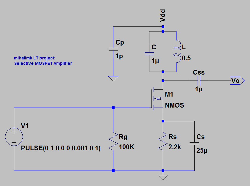
Picture 2: Selective MOSFET Amplifier with Simple Oscillation LC circuit
On the Picture 2 is shown the selective MOSFET amplifier with one simple oscillation circuit of parallel combination of capacitor C = 1uF and inductor coil L = 0.5 H and series resistance of Rs = 0.1 ohms. The pulse generator connected in this circuit has a role as a starting circuit. In other words, the pulse that it generated which in this case is with amplitude of 1 V and stays on for 1 ms, is needed for circuit to start oscillating. After the pulse, we have pure sinusoidal oscillation with period of about 4.5 ms. The output of the circuit is shown on the Picture 3. From this picture we can see that the amplitude of the oscillation is about 9 mV. The calculated period of the oscillation is 4.4 ms, and the frequency is 225.2 Hz. This circuit configuration is not well adjusted as a selective amplifier, so we can treat it as simple oscillator circuit at frequency of around 225 Hz. Anyway, the point here was to see the concept of the basic oscillation circuits and selective amplifiers.

Picture 3: The output voltage of the selective amplifier: oscillation signal
No comments:
Post a Comment