The pentode vacuum tube amplifier circuit configuration is shown on Picture 1. The pentode tube used in this circuit is the EL84 or 6BQ5 tube spice model. The heater circuit for the cathode is not shown in this symbol, but it's on 6.3 V AC or DC voltage and it consumes current of 760 mA. The power supply voltage for this circuit is Us = 450 V DC. This voltage is leaded to the anode of the pentode tube through the resistor Ra = 82 kOhms and to the screen electrode or grid 3 through the resistor Rs = 220 kOhms. The cathode is connected to the ground through the parallel combination of the resistor Rk = 2.2 kOhms and the electrolytic capacitor C3 = 270 uF. For the proper polarization of the grid 1 the resistors Rm = 1 MOhms and Rg = 10 kOhms take places. The input voltage signal is leaded to the grid of the pentode through the capacitor C1 and the resistor Rg. The output voltage is taken from the anode of the pentode through the capacitor C2 and is leaded to the load resistor Rload = 10 kOhms. The both coupling capacitors are C1 = C2 = 1 uF.

Picture 1: Pentode Tube Amplifier Circuit
Time-domain analysis
The results of the transient analysis in time domain for this circuit are shown on Picture 2. The green color line plot is the output voltage wave form and the blue color line plot is the input voltage wave form. Since the pentode tube is more powerful than the triode tube, we can consider that this circuit can be driven by the triode tube stage, so, as output power stage it can be excited with higher voltage level. In this case, the input voltage source is with sinusoidal waveform with amplitude of 1 V at frequency of 1 kHz. The output varies from about +/- 5.9 V amplitudes, it is phase inverted from the input. The voltage amplification of this circuit is about Av = 5.8, and the current amplification is about Ai = 584. These are the results from the simulation:
For Vi max = + 1 V => Vo min = - 6.02 V;
For Vi min = - 1 V => Vo max = + 5.85 V;
--> Av = 5.8 (approximate voltage amplification Av = Vo/Vi)
For Ic1 min = - 1 uA => IRl max = + 584 uA;
For IC1 max = + 1 uA => IRl min = - 602 uA;
--> Ai = 584 (approximate current amplification Ai = Io/Ii)
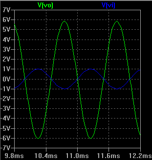
Picture 2: Transient analysis - input and output voltage wave forms (time-domain)
Frequency-domain analysis
The phase-frequency characteristics of this common cathode circuit were measured with AC analysis in LT spice. LT Spice computes the small signal AC behavior of the circuit linearized about its DC operating point. In this AC simulation were used these parameters:
Type of Sweep: Octave;
Number of points per octave: 1;
Start Frequency: 20 Hz;
Stop Frequency: 10 MHz;

Picture 3: AC Analysis - output voltage [dB] and its phase [degrees] (frequency-domain)
This circuit has a flat amplification for frequencies up to 1 MHz. The magnitude of the output voltage in this band is about + 15.5 dB. The magnitude decreases for 3 dB at frequency of 1.06 MHz with phase of -232.9 degrees and group delay of 100.4 ns. This is the high frequency limit for this circuit fH = 1.06 MHz. At frequency of 20 Hz the magnitude of the output voltage is 15 dB with phase of -159.4 degrees and group delay of 1.72 ms. At frequency of 10 MHz the magnitude of the output voltage is -8.8 dB with phase of -320.6 degrees and group delay of 4.9 ns. According to the results of the AC analysis this circuit has relatively flat voltage amplification for the audio signals and has no low frequency limit. The phase-frequency characteristics of the circuit is shown on the Picture 3.
No comments:
Post a Comment