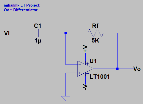
Picture 1: Differentiator
The differentiator circuit shown on Picture 1 is basically the same as the integrator circuit, just the resistor and capacitor has switched positions. Here, the capacitor is in the input loop of the circuit, so the input current is determined by the capacitor law, which looks like:
Ii = Ic = C*(dVi/dt)
Thus, for the output voltage we have:
Vo = -Rf*Ii = -Rf*C*(dVi/dt)
So, as we can see from the last relation, the output voltage of this circuit is the differential by time of the input voltage. On the Picture 2 are shown the input and output voltage wave forms of the differentiator circuit. The input is sinusoidal signal with amplitude of 100 mV at frequency of 500 Hz. The input signal is represented by the blue line plot and the output signal is represented by the green line plot.

Picture 2: Input and Output voltage wave forms of the differentiator
No comments:
Post a Comment