For purpose of generating signals with high or small pulse/pause relationship, the blocking oscillator with two accumulation elements is suitable circuit, as shown on Picture 1. The additional accumulation element in this circuit is the capacitor C1. Furthermore, at this blocking oscillator, the frequency of generated pulses can be changed, since the period when the transistor is blocked depends on the time constant R1*C1. So, changing the values of these elements, will change the frequency of the generated pulses.
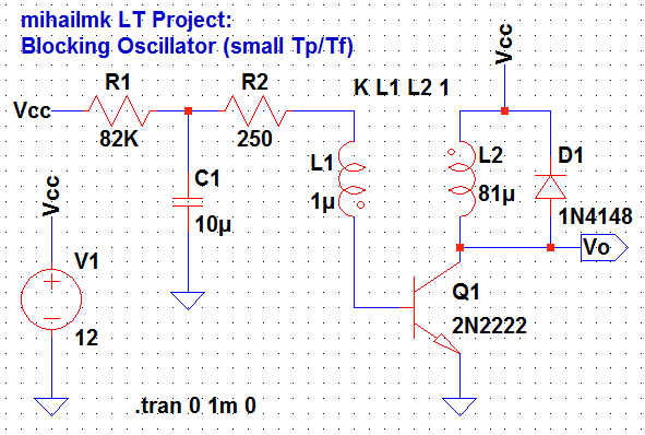
Picture 1: Blocking Oscillator circuit with two accumulation elements
Time-domain analysis
The results of the transient analysis for this circuit in time domain are shown on Picture 2. The output voltage Vo have low level periods of about 1.5 us when the voltage is about 123 mV, while the high level periods have duration of around 35.8 us and voltage values starts from 13 V and it's slowly falling to the value of 12.6 V. So, according to these results, the relationship between the periods of pulse and pause in output voltage is Tp/Tf = 35.8/1.5 = 23.86, which means is high.

Picture 2: Transient analysis - output voltage Vo wave form (time-domain)
Now, if we remove the diode D from the circuit, we will get the response which has small pulse/pause relationship. The wave form of this output voltage is shown on Picture 3. The time duration between the short pulses of the output voltage is around 4.61 us. After each high and short positive pulse, there is one short negative pulse of about -66 V, and after about 1.5 us the voltage cross the zero and goes into positive region with values around 4 mV and rising up to 450 mV at time region of 0.1 us before the next high peak. It's very interesting to notice here, that the positive peaks are to short in time, but extremely large in magnitude. As we can see from the plot on Picture 3, the starting peaks reach the voltage of around 4 KV (4000 V), which is very high and dangerous level. The time period when the peak voltage reaches values above 500 V is around 20 ns. So, if we chose this value as pulse period, then the relationship of pulse/pause for this circuit will be Tp/Tf = 0.02/4.61 = 0.004, and that's the desired very small value. However, this specific circuit generates these extremely high peaks just for the relatively short period of time. Namely, the peaks starts at values of around 4 KV and they decrease permanently, so after 5.56 ms the maximum values of the peaks falls below 50 V. At the time moment of 5.57 ms the circuit stops generating the extremely high voltage variations and oscillates around 12 V with magnitudes of around +/- 20 mV. So, this time region of extremely high voltage peaks it's kind of a transitional mode at the start of circuits work.

Picture 3: Transient analysis - output voltage Vo wave form without diode D (time-domain)
No comments:
Post a Comment