Ladder Logic Programming
A program consists of instructions that accomplish specific tasks. The degree of complexity of a PLC program depends upon the complexity of the application, the number and type of input and output devices, and the types of instructions used. Ladder logic (LAD) is one programming language used with PLCs. Ladder logic incorporates programming functions that are graphically displayed to resemble symbols used in hard-wired control diagrams.
The left vertical line of a ladder logic diagram represents the power or energized conductor. The output coil instruction represents the neutral or return path of the circuit. The right vertical line, which represents the return path on a hard-wired control line diagram, is omitted. Ladder logic diagrams are read from left-to-right and top-to-bottom. Rungs are sometimes referred to as networks. A network may have several control elements, but only one output coil.
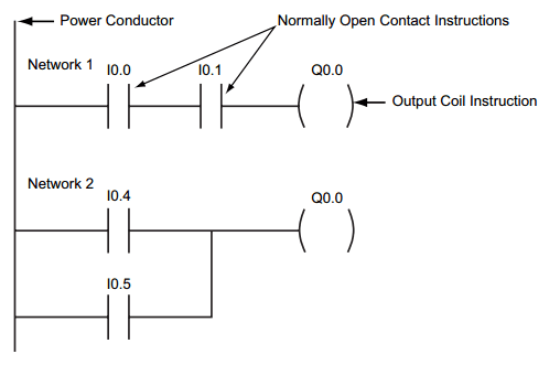
Picture 1: Ladder Logic Programming sample
Statement List and Function Block Diagrams
While ladder logic programs are still common, there are many other ways to program PLCs. Two other common examples are statement list and function block diagrams.
Statement list (STL) instructions include an operation and an operand. The operation to be performed is shown on the left. The operand, the item to be operated on, is shown on the right.
Function block diagrams (FBD) include rectangular functions with inputs shown on the left side of the rectangle and outputs shown on the right side.
In the following example (Picture 2), the program segments perform the same function.

Picture 2: STL, FBD, LAD samples
In addition to LAD, STL, and FBD, multiple other types of programming languages are used for PLCs. Each type of programming has its advantages and disadvantages. Factors such as application complexity, types of programming available for a specific PLC model, and user standards and preferences determine which type of programming is used for an application.
PLC Scan
The PLC program is executed as part of a repetitive process referred to as a scan. A PLC scan (Picture 3) starts with the CPU reading the status of inputs. Next, the application program is executed. Then, the CPU performs internal diagnostics and communication tasks. Finally, the CPU updates the status of outputs. This process repeats as long as the CPU in the run mode. The time required to complete a scan depends on the size of the program, the number of I/Os, and the amount of communication required.

Picture 3: PLC Scan Process
No comments:
Post a Comment