Motor Starter Example
A more practical, and only slightly more complex application is start-stop control of an AC motor. Before examining the PLC application, first consider a hardwired approach. The following line diagram (Picture 1) illustrates how a normally open and a normally closed push button might be connected to control a three-phase AC motor. In this example, a motor starter coil (M) is wired in series with a normally open, momentary Start push button, a normally closed, momentary Stop push button, and normally closed overload relay (OL) contacts.
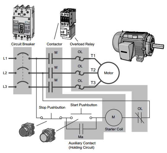
Picture 1: Motor Starter Example
Momentarily pressing the Start push button completes the path for current flow and energizes the motor starter (M). This closes the associated M and Ma (auxiliary contact located in the motor starter) contacts. When the Start button is released, current continues to flow through the Stop button and the Ma contact, and the M coil remains energized.
The motor will run until the normally closed Stop button is pressed, unless the overload relay (OL) contacts open. When the Stop button is pressed, the path for current flow is interrupted, opening the associated M and Ma contacts, and the motor stops.
PLC Motor Control
This motor control application can also be accomplished with a PLC. In the following example (Picture 2), a normally open Start push button is wired to the first input (I0.0), a normally closed Stop push button is wired to the second input (I0.1), and normally closed overload relay contacts (part of the motor starter) are connected to the third input (I0.2). These inputs are used to control normally open contacts in a line of ladder logic programmed into the PLC.

Picture 2: PLC Motor Control
Initially, I0.1 status bit is a logic 1 because the normally closed (NC) Stop push button is closed. I0.2 status bit is a logic 1 because the normally closed (NC) overload relay (OL) contacts are closed. I0.0 status bit is a logic 0, however, because the normally open Start push button has not been pressed. Normally open output Q0.0 contact is also programmed on Network 1 as a sealing contact. With this simple network, energizing output coil Q0.0 is required to turn on the motor.
Program Operation
When the Start push button is pressed, the CPU receives a logic 1 from input I0.0. This causes the I0.0 contact to close. All three inputs are now a logic 1.
The CPU sends a logic 1 to output Q0.0. The motor starter is energized and the motor starts.
The output status bit for Q0.0 is now a 1. On the next scan, when normally open contact Q0.0 is solved, the contact will close and output Q0.0 will stay on even if the Start push button is released.
When the Stop push button is pressed, input I0.1 turns off, the I0.1 contact opens, output coil Q0.0 de-energizes, and the motor turns off.
Adding Run and Stop Light Indicators
The application can be easily expanded to include indicator lights for run and stop conditions. In this example (Picture 3), a RUN indicator light is connected to output Q0.1 and a STOP indicator light is connected to output Q0.2.
The ladder logic for this application includes normally open Q0.0 contact connected on Network 2 to output coil Q0.1 and normally closed Q0.0 contact connected on Network 3 to output coil Q0.2. When Q0.0 is off, the normally open Q0.0 contact on Network 2 is open and the RUN indicator off. At the same time, the normally closed Q0.0 contact is closed and the STOP indicator is on.

Picture 3: Run and Stop Indicator states
When the Start button is pressed, the PLC starts the motor. Output Q0.0 is now on. Normally open Q0.0 contact on Network 2 is now closed and the RUN indicator is on. At the same time, the normally closed Q0.0 contact on Network 3 is open and the STOP indicator light connected to output Q0.2 is off.
Further Expansion
The PLC program can be further expanded to accommodate a wide variety of commercial and industrial applications (Picture 4). Start/Stop push buttons, selector switches, indicator lights, and signaling columns can be added. Motor starters can be added for control of additional motors. Over-travel limit switches can be added along with proximity switches for sensing object position. Various types of relays can be added to expand the variety of devices being controlled. As needed, expansion modules can be added to further increase the I/O capability. The applications are only limited by the number of I/Os and amount of memory available for the PLC.

Picture 4: Expansion Elements
No comments:
Post a Comment