The inflectional tangent model
In numerous technical applications, particularly in the areas of process or energy technology, the system step responses occur without any oscillation ratio and only display proportional or integral action in connection with dead time. The transient function shown on Picture 1 in the form of a linear dynamic model is therefore often used. The system behaviour is therefore considerably simplified, characterised by the three characteristic values: Proportional or integral coefficient, time delay and transient time. On Picture 1, these parameters are marked as:
>> K – proportional coefficient;
>> Tu – time delay;
>> Tg – transient time;
>> KIS = ∆h/∆t = K/Tg – Integral coefficient.

Picture 1: Frequently used transient function model (inflectional tangent model)
The inflectional tangent used to obtain the characteristic values Tu and Tg is for instance entered freehand into the experimentally determined step response. If this is subject to high-frequency interference, then a smoothing out should be carried out, if necessary by eye (or computerassisted). In the case of low frequency interference, the process cannot be evaluated. Here, a number of repetitions of the experiment and smoothing by means of averaging can be of help. The Table shown on Picture 2 contains the characteristic model values of typical controlled systems.

Picture 2: Model characteristic values of typical controlled systems
From the quotient Tg/Tu, it is incidentally already possible to estimate the degree of difficulty to be expected in the control of a system (Picture 3):
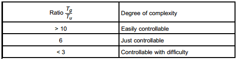
Picture 3: Evaluation of degree of complexity of closed-loop control
The total time constant model
Another simple basic model of proportional action controlled systems without oscillation ratio, which lends itself well for the controller design, can be determined in accordance with Strejc in the following way:
>> The times t20 or t80 are taken from the illustration of the system transient function, with which the function h(t) has achieved 20 % or 80 % of its final value (Picture 4):
Picture 4: Controlled system transient function
>> the transient behaviour of the system is then again described via three characteristic values:
K – Proportional coefficient of system;
T – System time constant;
Tt – System dead time.
Time constant T and dead time Tt are calculated from the time values t20 and t80 in accordance with the following formulae:
T = 0.721* (t80 -t20)
Tt = 1.161* t20 - 0.161* t80
The total of the two characteristic values T and Tt is referred to as total time constant TΣ.
No comments:
Post a Comment