In the experimental state, the flow control system consists of a piping system, with which the water is removed from and returned to a container via a centrifugal pump (see Picture 1). The automation task is to regulate the flow Q in the piping.

Picture 1: Schematic representation of flow control system
Theoretical model configuration
Leaving apart the hardware and software details, the flow behaviour in the flow control system can be represented in a considerably simplified manner as follows (Picture 2), this means:
>> ∆p0 = kpN^2 – Maximum delivery pressure of the centrifugal pump at speed N (for Q = 0);
>> ∆pStat = pg(hA - hW) for hA ∀ hW, otherwise zero – Differential pressure as a result of height difference;
>> ∆pi = kiQ^2 – Pressure drop as a result of "internal resistance" of centrifugal pump;
>> ∆pR = kR Q^2 – Pressure drop through the piping system;
>> ∆pV = KS Q^2/Kv^2 (Y) – Pressure drop through the control valve;
>> KV – Kv value;
>> Y – Valve travel.

Picture 2: Physical model of flow process in flow control system
Static model of controlled system
In the stationary state (Q = const.), there must be a balance between the pressures, this means:
o = ∆p0 − ∆pstat − ∆pi − ∆pR − ∆pV
or
0 = kpN^2 − ρg (hA − hW) − {ki + kR + KS * 1/KV^2(Y)} * Q^2
If a linear characteristic flow curve is assumed with:
KV (Y) = kY
in the operating range (0 to 100 %) of the valve, then the following relationship is obtained from these equations assuming a constant water level hW and constant speed N of the pump:
Q (Y) = √ { ( kp*N^2 − ρg*(hA − hw) ) / ( ki + kR + KS * 1/(k^2 * Y^2) }
Picture 3 illustrates the qualitative pattern of this characteristic curve.
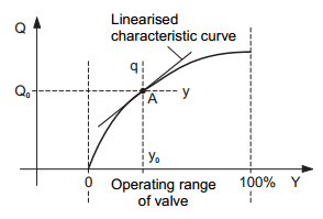
Picture 3: Steady-state characteristic curve of controlled system if control valve is used to control the flow rate
In the area of the operating point A (Q=Q0 + q, Y=Y0 + y), the following linear correlation then applies:
q = Ky (linearised model).
If the flow is regulated above the pump speed N, then the following linear relationship can be assumed in the operating range of the pump:
Q(N) = k1 + k2*N
between the correcting variable Pump Speed N and controlled variable Flow Q (see also Picture 4).

Picture 4: Steady-state characteristic curve of controlled system if pump is used to control the flow rate
Linear dynamic controlled system model
The flow control system for flow (input variable of valve position y, output variable of flow q) provides a good approximation of pure proportional behaviour without time delay. A change of the valve position results in a (practically) instant, proportional change in the flow. Transient phenomena caused by the acceleration of the volume of water in the piping system, can be disregarded here. However, the time delay between the actuation of the control equipment (standard voltage signal Ve) and the valve position y must not be ignored. Here, proportional action with delay of the first order is to be expected. Picture 5 illustrates the qualitative pattern of the step response of a transient element of this type.

Picture 5: Qualitative process of system step response
However, due to the arrangement of the piping system and the measuring technology and measured-value processing used, a (minor) system delay dead time Tt still has to be expected when the system is operated in practice, which will then have to be experimentally determined in the same way as the controlled system values K and T. The same deliberations apply with regard to the transient phenomena relating to the use of the centrifugal pump. Here it must be assumed that the pump speed variation does not immediately affect the flow but that, due to the pump design, acceleration processes in the moving volume of water will lead to delays in the process. The same deliberations as above apply with regard to the dead time Tt. All in all, these deliberations in the area of the operating point provide a qualitative dynamic system model (configuration model), which contains three parameters (Ks, Tt, T) still to be determined by experiment.
No comments:
Post a Comment