Output Filter in Class D Amplifier
The output filter is a low pass filter that reduces the switching frequency. When designing the filter, the load impedance is part of the equation. Thus, the load can seriously affect the frequency transfer. For different loudspeakers, the impedance over the audio range can vary from 1 Ω to as much as 30 Ω, with a phase from +56º to - 67º. Picture 1 shows the impedance of a 3-way loudspeaker system that was used in the listening tests.
Picture 1: Loudspeaker impedance
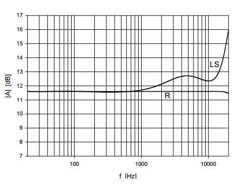
The output filter, however, is designed for a real and constant load impedance. The result of connecting the loudspeaker is shown in Picture 2. The flat line is the simulated transfer of an ideal class D filter followed by a fourth order Butterworth filter with a corner frequency of 30 kHz, loaded with the specified load impedance of 4 Ω. The other line shows what happens when the loudspeaker is connected. The transfer deviates several dB’s from the flat line. This will colour the sound impression. Another problem is that any non-linearities in the filter show up in the distortion figures.
Picture 2: Simulated class D frequency transfer with resistor and loudspeaker load
Feedback can reduce these problems considerably, but because of the phase shift, feedback after (part of) the filter is complicated. In general, the filter (or the filter in combination with lead compensation) must have a first order frequency transfer at 0 dB to ensure stable operation. This is extra complicated by the connected load, which is a part of the filter. High feedback factors can not be realised and feedback around a filter with more than 2-nd order behaviour is very rare. Even when these problems are overcome, the filter prevents further integration because it contains elements that can not be integrated on chip. For sufficient suppression of the carrier frequency, typically a fourth order filter is necessary. In this case, the amount of filtering in practical situations is limited by parasitic capacitances and resistances. Furthermore, two coils and two capacitors are already considered to be many external components. Using only a second order filter is a solution, but the amount of switching ripple can cause EMI problems and the application area of the amplifier will be limited.
Subscribe to:
Post Comments (Atom)


No comments:
Post a Comment