The IEC signal is suitable for measuring the efficiency of audio amplifiers, but for prediction purposes it is less ideal. The signal is difficult to generate when the efficiency of an amplifier has to be simulated in a circuit simulator. In circuit simulators, transient noise sources are rarely available, and usually take a long simulation time. Also, for long term testing (reliability), a noise generator is often not available. A simple, periodic test signal would be welcome. The most important quality is a controlled amplitude probability density function. Suppose the signal is V = f(t), and that it is monotonously rising on t∈ [0,t1]. The distribution function is the chance that f(t) is smaller than a certain value V, is:
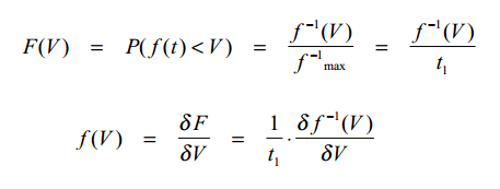
Picture 1: The distribution function F(V) and The probability density function f(V)
As it can be seen from Picture 1, the probability density function f(V) is the derivative of the distribution function F(V). So if we want to design a signal with a gaussian amplitude probability density function, we know that f(V) is a gaussian curve. Then, f^-1(V) is the integral of a gaussian curve, which is the normal distribution function. Thus, f(t) must be the inverse of the normal distribution function. Picture 2 shows a possible time function.

Picture 2: Signal with a gaussian amplitude distribution
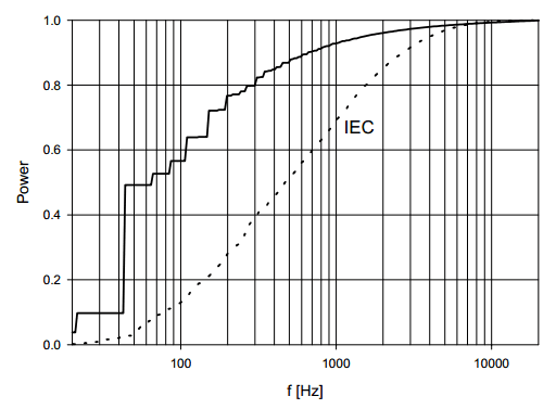
Picture 3: Frequency distribution of a signal with gaussian amplitude distribution (Picture 2), and of the IEC signal
Unfortunately, the corresponding frequency distribution, shown on Picture 3, is not OK. The higher frequencies are relatively weak. Although the period time of the signal could be chosen a little shorter, the frequency distribution can never match that of the IEC signal. Synthesising a signal that also has a controlled frequency distribution is not straightforward. The signal shown on Picture 2 or a 1/√t signal (which has a 1/f power distribution) can be filtered to produce the signal shown on Picture 4. This signal has a correct frequency distribution, but the amplitude distribution is too wide due to much power in the high amplitudes. Also, the frequency distribution alters when the signal clips, so testing for higher output powers is not possible. When the frequency distribution is of prime importance, the signal of Picture 4 can be useful. However, in practice its application will be very limited.

Picture 4: A signal with an IEC 268 frequency distribution
Conclusion
It seems hardly possible to construct a simple periodic test signal that has all the properties we need to simulate music and speech. Often, however, the amplitude distribution is the most important property. Class G amplifiers, for instance, are not very sensitive to the exact frequency of their output signal. In that case, the signal of Picture 2 is advantageous owing to its very short repetition frequency. In a circuit simulator, a single period will suffice to give a good dissipation prediction.
No comments:
Post a Comment