There are numerous modulators, and here it is not objective to give an extensive overview, only the basic topologies are discussed.
PDM modulators
PDM modulators have resulted from the digital signal processing domain. In more and more equipment, the signal is available in digital form. For a switching amplifier it must be converted into a 1 bit signal at a high frequency. Sometimes, as with DSD audio data, this is even the native format. The output stage acts as a 1 bit D/A converter. Because the length of each bit is constant, and only the presence or non-presence of a bit is controlled, this is called Pulse Density Modulation (PDM). To convert a multi-bit signal to a 1-bit signal, oversampled noise shaping is used. Picture 1 shows a general noise shaper.
Picture 1: Noise shaper
The input signal Bin(z) has a larger number of bits than Bout(z). (When the input signal is analogue, a similar structure in the analogue domain constitutes a sigma-delta modulator). The block called "Quantizer" reduces the number of bits by simply passing only the most significant bits to Bout(z). The least significant bits, which are the error, are added to the input after passing through a transfer function J(z). It is easy to calculate Bout:
Bout(z) = Bin(z) - ε(z)(1 - J(z))
Suppose J(z) = z-1, one clock delay. The system is now a first-order noise shaper. Bin(z) is a 16 bit signal at 256fs and Bout is a 1 bit signal at 256fs. In that case, the quantizer transfers 1 bit to the output. The other 15 bits are the error signal. Bout equals:
Bout(z) = Bin(z) - ε(z)(1 - z^-1)
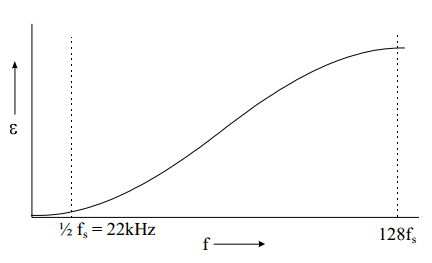
With z = e^( 2πj(f/256fs)), we see that for low frequencies (audio) the error in the output signal approaches zero. The error reaches a maximum for f = 128fs. See Picture 2.
Picture 2: Noise distribution as a function of frequency
Applying Bout to a 1 bit D/A converter and filtering above 20 kHz reconstructs the original signal. In the time domain such a noise shaper is a way to convert resolution in the amplitude domain to resolution in the time domain. It outputs bits at high speed in such a way that the average is the intended output (which has a higher amplitude resolution). This way it is also easy to see that although the D/A converter is only 1 bit, it should have a 16 bit accuracy.
To convert the audio signal to 256fs, an oversampling interpolating filter must proceed the noise shaper. A two times oversampling filter works as follows. Suppose the spectrum of the signal sampled at fs looks like Picture 3. This signal is converted to a sampling frequency of 2fs by inserting a sample of value zero after every original sample. See Picture 4. Because every sample is a Dirac pulse of proportional height, the frequency spectrum stays exactly the same.
Picture 3: Spectrum of the signal
Picture 4: Inserting zero samples
Next, the signal is applied to a digital filter at 2fs that filters out the middle replica, see Picture 5. After that, the frequency spectrum of the signal looks exactly like it has been sampled at 2fs. These techniques, oversampling interpolating filtering and noise shaping are essential for all digital PDM systems, although the exact realisation may vary.
Picture 5: Filtering out the middle replica
Assume, the 256 times oversampling for a CD player D/A converter is done in two stages. A four times oversampling filter is followed by a 64 times linear interpolator. The direct use of a 256 times oversampling filter is also possible, but the filter would be very large. A linearly interpolating filter is easier to build, and at 4fs the distortion that it creates has only little effect in the audio band. Then, at 256fs, a second order noise shaper suffices to get a 1 bit signal with 16 bit resolution in the audio band. Unfortunately 256fs = 11MHz which is too high for power switching.
Another possibility is to use only 32fs with an eighth order noise shaper.
Noise shapers with a higher order than three are prone to instability, and it is necessary to manipulate the system when it becomes potentially unstable. Extensive simulations are necessary for evaluation. Even in this case, the switching frequency is 1.4 MHz. The high switching frequencies are a general problem of PDM modulators. Bit-flipping techniques can reduce the average frequency at which the output changes somewhat.
Digital PWM modulators
Digital PWM modulators offer a lower switching frequency than PDM modulators. The Pulse Amplitude Modulated (PAM) samples are converted to PWM. This could be done by giving each pulse a length that is proportional to the original amplitude. However, for CD quality the internal clock frequency would have
to be 2^16 * 44.1 kHz = 2.9 GHz, which is way too high. Furthermore, the frequency spectrum of the PWM signal would not equal that of the PAM signal. This can be calculated, but for a better understanding it is best to realise that natural sampling yields the best results because it does not introduce harmonic distortion. In natural sampling, the audio signal is compared to a triangle or sawtooth waveform (more details below). When we convert a digital PAM signal directly to PWM, it looks as if, looking in the analogue domain, we compared the sawtooth waveform to a step-like representation of the signal instead of the signal itself. This is called uniform sampling. See Picture 6. It introduces harmonic distortion, which depends on many factors including the signal frequency, the switching frequency and the modulation depth.
Picture 6: Natural sampling versus uniform sampling
To approximate natural sampling, linear or higher order interpolation between two or more samples is used to approach the natural PWM pulse width. When the pulse width has been calculated, the sample instant can be the beginning or the end of the pulse (single sided modulation) or the middle (double sided modulation). There are more aspects that deserve attention, but a full discussion of these would be beyond the scope of this article.
Analogue PWM modulators
In the analogue domain a PWM signal can be generated by comparing the audio signal to a triangle or sawtooth waveform. This technique, called natural sampling, is the basis of almost all analogue modulators. See Picture 7. When the momentary value of the input signal is larger than the triangle, the output of the switch is high. It is easy to see that in this way the pulse width at the output is proportional to the input voltage. The modulator does not introduce harmonic distortion, only (multiples of) the carrier frequency and (multiples of) harmonics of the modulating frequency around the carrier.
Picture 7: Open-loop class D modulator
The main problem is the lack of feedback. Output stage inaccuracies, nonlinearities, timing errors and supply voltage variations all contribute to the distortion. We will discuss feedback here, as it is so closely related to the modulator. Picture 8 shows a modulator with feedback. Both inputs to the comparator have triangular waveforms. Picture 9 shows the waveforms for zero and positive output voltage. At zero output voltage, the feedback signal intercepts the reference triangle in such a way that the duty cycle is 50 %. When the output voltage is not zero, the rising and falling slope of the feedback triangle are different, leading to a larger (or smaller) duty cycle.
Picture 8: Modulator with feedback
Picture 9: Signals at the input of the comparator of the feedback modulator
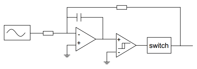
The slew rate of the feedback signal must always be smaller than the slew rate of the reference triangle. Otherwise, the amplifier starts oscillating at a very high frequency. This constitutes a compromise between switching frequency and loop gain. The slew rate requirement can roughly be translated to the demand that the loop gain of the amplifier at the switching frequency is smaller than 0.5. Thanks to the integrator, the open loop frequency transfer of the amplifier is first order, so that the loop gain at a certain frequency has a maximum that is related to the switching frequency. A way to get more loop gain at low (audio) frequencies is by introducing a range with second order frequency response in the loop. As long as the loop gain is back to first order at 0 dB, stability is ensured. This can be done in the modulator by adding a second integrator before the comparator while bypassing it for high frequencies. In practical realisations of a feedback modulator, the triangle is generated by adding a square wave to the input of the integrator. The feedback properties of this type of modulator can also be used when the input signal is generated by a digital modulator. Because in that case the bitstream is already clocked, the negative input of the comparator can be tied to ground. Other techniques, like the one cycle control technique or pulse edge delay error correction, are similar to this modulator in their attempt to control the integral of the switched output voltage.
The high frequency oscillation that occurs in a feedback modulator when the feedback signal is too large, is exploited in the self-oscillating class D modulator. See Picture 10. The comparator is equipped with some hysteresis to control the switching frequency. Other factors that influence the switching frequency are the integrator time constant and the output voltage. For large output voltages, the frequency approaches zero. This can cause aliasing problems that can be overcome by using a comparator with a variable hysteresis dependent on the input voltage. In that way the oscillator frequency is kept constant over a wide range of output voltages.
Picture 10: Self oscillating class D modulator
In the situations above, feedback is successfully taken before the output filter. The combination with feedback after the filter is more troublesome.


No comments:
Post a Comment