It is not necessary to use two power supplies like in class G amplifier. Because the signal peaks generally last only a short time, the energy can be supplied by a capacitor. This technique is referred to as Class H (Picture 1).

Picture 1: Class H amplifier
During low output voltages, the switch is in the position as drawn in Picture 1. During signal peaks the switch lifts the lower side of the elco to the power supply, such that the upper output transistor sees a voltage of approximately 2Vdd. The time that the signal is "high" should not be too long. A large elco is required for high power at low frequencies. Switching according to the envelope of the signal, as is sometimes done with class G amplifiers, is riskier as it is impossible to tell how long an envelope will last.
The advantage of class H is that only one power supply is needed. As such it is ideal for car audio applications. To prevent the need for four lifting elcos, it is then built like a bridge amplifier with a signal dependent common mode level. Picture 2 shows a class H bridge amplifier. The common mode level is normally half the supply voltage. When the load voltage must be higher than Vdd, the common mode level of the bridge is increased such that one half of the bridge remains at a constant voltage close to ground and the other half gets the lifted supply voltage. See Picture 3 for the waveforms of the two bridge halves for a sinusoidal output.
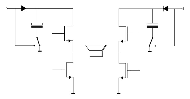
Picture 2: Class H Bridge amplifier

Picture 3: Wave forms of both bridge halves for a sinusoidal output
For normal audio signals, and even for a rail-to-rail sinewave, only one lifting circuit would suffice. In practice this is not implemented, because it’s a bad habit to test audio amplifiers with near rail-to-rail squarewaves, which give the lift elco not enough time to recharge.
No comments:
Post a Comment