The construction of the Tesla induction motor was described in Tesla Poly-Phase Induction Motors article. In this article will be represented the theory of operation of the poly-phase induction motor. A short explanation of operation is that the stator creates a rotating magnetic field which drags the rotor around. The theory of operation of induction motors is based on a rotating magnetic field. One means of creating a rotating magnetic field is to rotate a permanent magnet as shown on Picture 1 below. If the moving magnetic lines of flux cut a conductive disk, it will follow the motion of the magnet. The lines of flux cutting the conductor will induce a voltage - and consequent current flow 00 in the conductive disk.

Picture 1: Rotating magnetic field produces torque in conductive disk
This current flow creates an electromagnet whose polarity opposes the motion of the permanent magnet - Lenz's Law. The polarity of the electromagnet is such that it pulls against the permanent magnet. The disk follows with a little less speed than the permanent magnet.
The torque developed by the disk is proportional to the number of flux lines cutting the disk and the rate at which it cuts the disk. If the disk were to spin at the same rate as the permanent magnet, there would be no flux cutting the disk, no induced current flow, no electromagnet field, no torque. Thus, the disk speed will always fall behind that of the rotating permanent magnet so that lines of flux cut the disk induce a current and create an electromagnetic field in the disk, which follows the permanent magnet. If a load is applied to the disk, slowing it, more torque will be developed as more lines of flux cut the disk. Torque is proportional to slip, the degree to which the disk falls behind the rotating magnet. More slip corresponds to more flux cutting the conductive disk, developing more torque.
An analog automotive eddy current speedometer is based on the principle illustrated above. With the disk restrained by a spring, disk and needle deflection is proportional to magnet rotation rate. A rotating magnetic field is created by 2 coils placed at right angles to each other, driven by currents which are 90 degrees out-of-phase. This should not be surprising if you are familiar with oscilloscope Lissajous patterns.
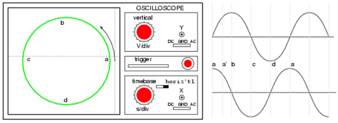
Picture 2: Out-of-phase (90 degrees) sine waves produce circular Lissajous pattern
On Picture 2 above, a circular Lissajous is produced by driving the horizontal and vertical oscilloscope inputs with 90 degrees out-of-phase sine waves. Starting at (a) with maximum “X” and minimum “Y” deflection, the trace moves up and left toward (b). Between (a) and (b), the two wave forms are equal to 0.707 V peak at 45 degrees. This point (0.707, 0.707) falls on the radius of the circle between (a) and (b) The trace moves to (b) with minimum “X” and maximum “Y” deflection. With maximum negative “X” and minimum “Y” deflection, the trace moves to (c). Then with minimum “X” and maximum negative “Y”, it moves to (d), and on back to (a), completing one cycle.

Picture 3: X-axis sine and Y-axis cosine trace circle
Picture 3 above shows the two 90 degrees phase-shifted sine waves applied to oscilloscope deflection plates which are at right angles in space. If this were not the case, a one-dimensional line would display. The combination of 90 degrees phased sine waves and right angle deflection results in a 2-dimensional pattern - a circle. This circle is traced out by a counter-clockwise rotating electron beam.
For reference, Picture 4 below shows why in-phase sine waves will not produce a circular pattern. Equal “X” and “Y” deflection moves the illuminated spot from the origin at (a) up to right (1,1) at (b) … back down left to origin at (c) … down left to (-1.-1) at (d) … and back up right to origin. The line is produced by equal deflections along both axes; y=x is a straight line.

Picture 4: No circular motion from in-phase wave forms (oscilloscope patern)
If a pair of 90 degrees out-of-phase sine waves produces a circular Lissajous, a similar pair of currents should be able to produce a circular rotating magnetic field. Such is the case for a 2-phase motor. By analogy, 3 windings placed 120 degrees apart in space and fed with corresponding 120 degrees phased currents will also produce a rotating magnetic field.

Picture 5: Rotating magnetic field from 90 degrees phased sine waves
As the 90 degrees phased sine waves, shown on Picture 5 above, progress from points (a) through (d), the magnetic field rotates counterclockwise (figures a-d) as follows:
● (a) φ-1 maximum, φ-2 zero;
● (a') φ-1 70%, φ-2 70%;
● (b) φ-1 zero, φ-2 maximum;
● (c) φ-1 maximum negative, φ-2 zero;
● (d) φ-1 zero, φ-2 maximum negative;
No comments:
Post a Comment