Some induction motors can draw over 1,000% of full-load current during starting (though a few hundred percent is more common). Small motors of a few kilowatts or smaller can be started by direct connection to the power line. Starting larger motors can cause line voltage sag, affecting other loads. Motor-start rated circuit breakers (analogous to "slow blow" fuses) should replace standard circuit breakers for starting motors of a few kilowatts. This breaker accepts high over-current for the duration of starting.
Picture 1: Autotransformer induction motor starter
Motors over 50 kW use motor starters to reduce line current from several hundred to a few hundred percent of full-load current. An intermittent duty autotransformer may reduce the stator voltage for a fraction of a minute during the start interval, followed by application of full line voltage as shown on Picture 1 above. Closure of the S contacts applies reduced voltage during the start interval. The S contacts open and the R contacts close after starting. This reduces starting current to, say, 200% of full-load current. Since the autotransformer is only used for the short start interval, it may be sized considerably smaller than a continuous duty unit.
Running 3-phase motors on 1-phase
3-phase motors will run on single phase as readily as single-phase motors. The only problem for either motor is starting. Sometimes 3-phase motors are purchased for use on single-phase if 3-phase power is anticipated. The power rating needs to be 50% larger than for a comparable single phase motor to make up for one unused winding. Single phase is applied to a pair of windings simultaneous with a start capacitor in series with the third winding. The start switch is opened upon motor start, as shown on Picture 2 below. Sometimes a smaller capacitor than the start capacitor is retained while running.

Picture 2: Starting a 3-phase motor on single phase
The circuit for running a 3-phase motor on single phase is known as “add a phase” or various other brand names. “Add a phase” supplies a phase approximately midway 90 degrees between the 180 degrees single-phase power source terminals.
Speed control with multiple fields
Induction motors may contain multiple field windings. For example, a 4-pole and an 8-pole winding corresponding to 1,800 and 900 rpm synchronous speeds. Energizing one field or the other is less complex than rewiring the stator coils, as shown on Picture 3 below.
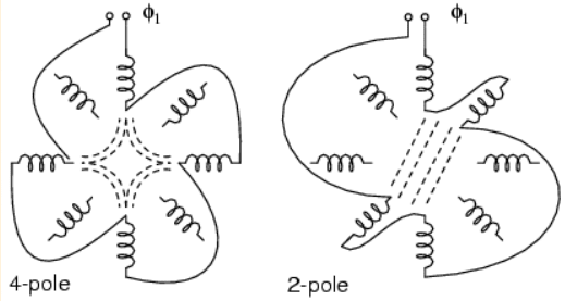
Picture 3: Multiple fields allow speed change
If the field is segmented with leads brought out, it may be rewired (or switched) from 4-pole to 2- pole as shown above for a 2-phase motor. The 22.5o segments are switchable to 45o segments. Only the wiring for one phase is shown above for clarity. Thus, our induction motor may run at multiple speeds. When switching the above 60 Hz motor from 4 poles to 2 poles, the synchronous speed increases from 1,800 rpm to 3,600 rpm. If the motor is driven by 50 Hz, the corresponding 4-pole and 2-pole synchronous speeds would be:
Ns = 120 f/P = 120 x 50/4 = 1,500 rpm (4-pole)
Ns = 3,000 rpm (2-pole)
Speed control with variable voltage
The speed of small squirrel cage induction motors for applications such as driving fans may be changed by reducing the line voltage. This reduces the torque available to the load which reduces the speed. The torque of motor expressed in % is shown on Picture 4.
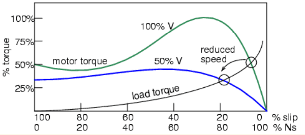
Picture 4: Variable voltage controls induction motor speed
Electronic speed control
Modern solid-state electronics increase the options for speed control. By changing the 50 or 60 Hz line frequency to higher or lower values, the synchronous speed of the motor may be changed. However, decreasing the frequency of the current fed to the motor also decreases reactance XL which increases the stator current. This may cause the stator magnetic circuit to saturate with disastrous results. In practice, the voltage to the motor needs to be decreased when frequency is decreased.

Picture 5: Electronic variable speed drive
Conversely, the drive frequency may be increased to increase the synchronous speed of the motor. However, the voltage needs to be increased to overcome increasing reactance to keep current up to a normal value and maintain torque. The inverter (Picture 5 above) approximates sine-waves to the motor with pulse width modulation outputs. This is a chopped waveform which is either 'on' or 'off', 'high' or 'low' with the percentage of 'on' time corresponds to the instantaneous sine wave voltage. Once electronics is applied to induction motor control, many control methods are available varying from the simple to complex:
Summary for Speed control:
● Scalar Control: Low-cost method described above to control only voltage and frequency without feedback.
● Vector Control (also known as vector phase control): The flux and torque producing components of stator current are measured or estimated on a real-time basis to enhance the motor torque-speed curve. This is computation-intensive.
● Direct Torque Control: An elaborate adaptive motor model allows more direct control of flux and torque without feedback. This method quickly responds to load changes.
Short Summary for Tesla Poly-Phase Induction Motors:
● A poly-phase induction motor consists of a polyphase winding embedded in a laminated stator and a conductive squirrel cage embedded in a laminated rotor.
● 3-phase currents flowing within the stator create a rotating magnetic field which induces a current, and consequent magnetic field in the rotor. Rotor torque is developed as the rotor slips a little behind the rotating stator field.
● Unlike single-phase motors, poly-phase induction motors are self-starting.
● Motor starters minimize loading of the power line while providing a larger starting torque than required during running. Starters are only required for large motors.
● Multiple field windings can be rewired for multiple discrete motor speeds by changing the number of poles.
No comments:
Post a Comment