Motor Speed
The rotation rate of a stator rotating magnetic field is related to the number of pole pairs per stator phase. The “full speed” (Picture 1 below) has a total of 6 poles or 3 pole-pairs and 3 phases. However, there is but one pole pair per phase - the number we need. The magnetic field will rotate once per sine wave cycle.
In the case of 60 Hz power, the field rotates at 60 times per second or 3,600 revolutions per minute (rpm). For 50 Hz power, it rotates at 50 rotations per second or 3,000 rpm. The 3,600 and 3,000 rpm are the synchronous speed of the motor. Though the rotor of an induction motor never achieves this speed, it certainly is an upper limit. If we double the number of motor poles, the synchronous speed is cut in half because the magnetic field rotates 180 degrees in space for 360 degrees of electrical sine wave.

Picture 1: Doubling the stator poles halves the synchronous speed: Full speed & Half speed stator windings
The synchronous speed is given by:
Ns = 120·f/P
where Ns is a synchronous speed in rpm, f is a frequency of applied power in Hz, and P is a total number of poles per phase (a multiple of 2).
Example:
The “half speed” Picture 1 above has 4 poles per phase (3-phase). The synchronous speed for 50 Hz power is:
S = 120·x 50/4 = 1500 rpm
The short explanation of the induction motor is that the rotating magnetic field produced by the stator drags the rotor around with it. The longer more correct explanation is that the stator's magnetic field induces an alternating current into the rotor squirrel cage conductors which constitutes a transformer secondary. This induced rotor current in turn creates a magnetic field.
The rotating stator magnetic field interacts with this rotor field. The rotor field attempts to align with the rotating stator field. The result is rotation of the squirrel cage rotor. If there were no mechanical motor torque load, no bearing, windage, or other losses, the rotor would rotate at the synchronous speed. However, the slip between the rotor and the synchronous speed stator field develops torque. It is the magnetic flux cutting the rotor conductors as it slips which develops torque. Thus, a loaded motor will slip in proportion to the mechanical load. If the rotor were to run at synchronous speed, there would be no stator flux cutting the rotor, no current induced in the rotor, no torque.
Motor Torque
When power is first applied to the motor, the rotor is at rest while the stator magnetic field rotates at the synchronous speed Ns. The stator field is cutting the rotor at the synchronous speed Ns. The current induced in the rotor shorted turns is maximum as is the frequency of the current (the line frequency). As the rotor speeds up, the rate at which stator flux cuts the rotor is the difference between synchronous speed Ns and actual rotor speed N (or Ns - N). The ratio of actual flux cutting the rotor to synchronous speed is defined as slip:
s = (Ns - N) / Ns
where Ns is synchronous speed and N is rotor speed.
The frequency of the current induced into the rotor conductors is only as high as the line frequency at motor start, decreasing as the rotor approaches synchronous speed. Rotor frequency is given by:
fr = s·f
where s is slip and f is stator power line frequency.
Slip at 100% torque is typically 5% or less in induction motors. Thus for f = 50 Hz line frequency, the frequency of the induced current in the rotor fr = 0.05·x 50 = 2.5 Hz. Why is it so low? The stator magnetic field rotates at 50 Hz. The rotor speed is 5% less. The rotating magnetic field is only cutting the rotor at 2.5 Hz. The 2.5 Hz is the difference between the synchronous speed and the actual rotor speed. If the rotor spins a little faster, at the synchronous speed, no flux will cut the rotor at all (fr = 0 ).
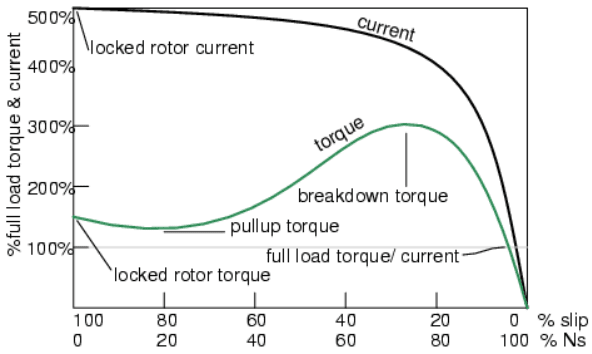
Picture 2: Torque and Current vs Slip[%]. Ns = [%] of Synchronous Speed
The above graph on Picture 2 shows that starting torque known as Locked Rotor Torque (LRT) is higher than 100% of the Full Load Torque (FLT) -- the safe continuous torque rating. The Locked Rotor Torque is about 175% of FLT for the example motor graphed above. Starting current known as Locked Rotor Current (LRC) is 500% of Full Load Current (FLC) -- the safe running current. The current is high because this is analogous to a shorted secondary on a transformer.
As the rotor starts to rotate, the torque may decrease a bit for certain classes of motors to a value known as the Pull-Up Torque. This is the lowest value of torque ever encountered by the starting motor. As the rotor gains 80% of synchronous speed, torque increases from 175% up to 300% of the Full Load Torque. This breakdown torque is due to the larger than normal 20% slip. The current has decreased only slightly at this point. But it will decrease rapidly beyond this point. As the rotor accelerates to within a few percent of synchronous speed, both torque and current will decrease substantially. Slip will be only a few percent during normal operation. For a running motor, any portion of the torque curve below 100% rated torque is normal. The motor load determines the operating point on the torque curve.
While the motor torque and current may exceed 100% for a few seconds during starting, continuous operation above 100% can damage the motor. Any motor torque load above the breakdown torque will stall the motor. The torque, slip, and current will approach zero for a “no mechanical torque” load condition. This condition is analogous to an open secondary transformer.
There are several basic induction motor designs showing considerable variation from the torque curve above. The different designs are optimized for starting and running different types of loads. The Locked Rotor Torque (LRT) for various motor designs and sizes ranges from 60% to 350% of Full Load Torque (FLT). Starting current or locked rotor current (LRC) can range from 500% to 1400% of full load current (FLC). This current draw can present a starting problem for large induction motors.
No comments:
Post a Comment