Standard Motor Designs
Motors are designed with speed-torque characteristics to match the requirements of common applications. The four standard NEMA motor designs, A, B, C, and D, have different characteristics. This article provides descriptions for each of these motor designs with emphasis on NEMA design B, the most common three-phase AC induction motor design.
Speed-Torque Curve for NEMA B Motor
Because motor torque varies with speed, the relationship between speed and torque is often shown in a graph, called a speed-torque curve. This curve shows the motor’s torque, as a percentage of full-load torque, over the motor’s full speed range, shown as a percentage of its synchronous speed. The following speed-torque curve shown on Picture 1 is for a NEMA B motor. NEMA B motors are general purpose, single speed motors suited for applications that require normal starting and running torque, such as fans, pumps, lightly-loaded conveyors, and machine tools. Using a 30 HP, 1765 RPM NEMA B motor as an example, full-load torque can be calculated by transposing the formula for horsepower:
HP = (Torque[lb-ft] x Speed[RPM])/5252 => Torque = 89.3 lb-ft

Picture 1: NEMA B Motor speed-torque curve
Starting Torque
Starting torque, also referred to as locked rotor torque, is the torque that the motor develops each time it is started at rated voltage and frequency. When voltage is initially applied to the motor’s stator, there is an instant before the rotor turns. At this instant, a NEMA B motor develops a torque approximately equal to 150% of full-load torque. For the 30 HP, 1765 RPM motor used in this example, that’s equal to 134.0 lb-ft of torque (Picture 2).

Picture 2: Starting torque
Pull-up Torque
As the motor picks up speed, torque decreases slightly until point B on the graph is reached (Picture 3). The torque available at this point is called pull-up torque. For a NEMA B motor, this is slightly lower than starting torque, but greater than full-load torque.
Breakdown Torque
As speed continues to increase from point B to point C (see Picture 3), torque increases up to a maximum value at approximately 200% of full-load torque. This maximum value of torque is referred to as breakdown torque. The 30 HP motor in this example has a breakdown torque of approximately 178.6 lb-ft.

Picture 3: Pull-up and Breakdown torque
Full-Load Torque
Torque decreases rapidly as speed increases beyond breakdown torque until it reaches full-load torque at a speed slightly less than 100% of synchronous speed (Picture 4). Full-load torque is developed with the motor operating at rated voltage, frequency, and load. The motor in this example has a synchronous speed of 1800 RPM and a full-load speed of 1765 RPM. Therefore, its slip is 1.9%.

Picture 4: Full-load torque
Speed-torque curves are useful for understanding motor performance under load. The following speed-torque curve on Picture 5 shows four load examples. This motor is appropriately sized for constant torque load 1 and variable torque load 1. In each case, the motor will accelerate to its rated speed. With constant torque load 2, the motor does not have sufficient starting torque to turn the rotor. With variable torque load 2, the motor cannot reach rated speed. In these last two examples, the motor will most likely overheat until its overload relay trips.
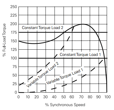
Picture 5: Constant and variable torque loads
Starting Current and Full-Load Current
Starting current, also referred to as locked rotor current, is the current supplied to the motor when the rated voltage is initially applied with the rotor at rest (Picture 6). Full-load current is the current supplied to the motor with the rated voltage, frequency, and load applied and the rotor up to speed. For a NEMA B motor, starting current is typically 600-650% of full-load current. Knowledge of the current requirements for a motor is critical for the proper application of over-current protection devices.

Picture 6: Starting and Full-load current
NEMA A Motor
NEMA A motors are the least common design. NEMA A motors have a speed-torque curve similar to that of a NEMA B motor, but typically have higher starting current. As a result, overcurrent protection devices must be sized to handle the increased current. NEMA A motors are typically used in the same types of applications as NEMA B motors.
NEMA C Motor
NEMA C motors are designed for applications that require a high starting torque for hard to start loads, such as heavily-loaded conveyors, crushers and mixers. Despite the high starting torque, these motors have relatively low starting current. Slip and full-load torque are about the same as for a NEMA B motor. NEMA C motors are typically single speed motors which range in size from approximately 5 to 200 HP. The following speed-torque curve shown on Picture 7 is for a 30 HP NEMA C motor with a full-load speed of 1765 RPM and a full-load torque of 89.3 lb-ft. In this example, the motor has a starting torque of 214.3 lb-ft, 240% of full-load torque and a breakdown torque of 174 lb-ft.

Picture 7: NEMA C Motor speed-torque curve
NEMA D Motor
The starting torque of a NEMA design D motor is approximately 280% of the motor’s full-load torque. This makes it appropriate for very hard to start applications such as punch presses and oil well pumps. NEMA D motors have no true breakdown torque. After starting, torque decreases until full-load torque is reached. Slip for NEMA D motors ranges from 5 to 13%.
The following speed torque curve shown on Picture 8 is for a 30 HP NEMA D motor with a full-load speed of 1656 RPM and a full load torque of 95.1 lb-ft. This motor develops approximately 266.3 lb-ft of starting torque.

Picture 8: NEMA D Motor speed-torque curve
https://build-its.blogspot.com/
ReplyDelete