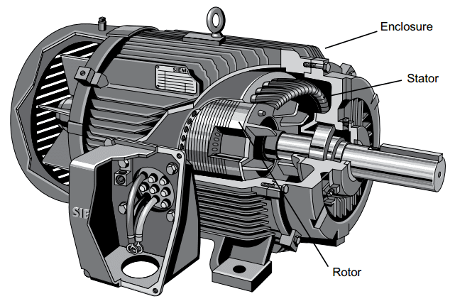
Three-phase AC induction motors are commonly used in industrial applications. This type of motor has three main parts: rotor, stator and enclosure (Picture 1). The stator and rotor do the work, and the enclosure protects the stator and rotor.
Picture 1: Main parts of AC motor: rotor, stator and enclosure
Stator Core
The stator is the stationary part of the motor’s electromagnetic circuit. The stator core is made up of many thin metal sheets, called laminations (Picture 2). Laminations are used to reduce energy loses that would result if a solid core were used.
Picture 2: Stator Lamination
Stator Windings
Stator laminations are stacked together forming a hollow cylinder. Coils of insulated wire are inserted into slots of the stator core. When the assembled motor is in operation, the stator windings (Picture 3 and Picture 4) are connected directly to the power source. Each grouping of coils, together with the steel core it surrounds, becomes an electromagnet when current is applied. Electromagnetism is the basic principle behind motor operation.
Picture 3: Stator Windings (Partially completed)
Picture 4: Stator Windings (Completed)
Rotor Construction
The rotor is the rotating part of the motor’s electromagnetic circuit (Picture 5). The most common type of rotor used in a three-phase induction motor is a squirrel cage rotor. The squirrel cage rotor is so called because its construction is reminiscent of the rotating exercise wheels found in some pet cages. A squirrel cage rotor core is made by stacking thin steel laminations to form a cylinder.
Picture 5: Rotor
Rather than using coils of wire as conductors, conductor bars are die cast into the slots evenly spaced around the cylinder. Most squirrel cage rotors are made by die casting aluminum to form the conductor bars. Manufacturers also makes motors with diecast copper rotor conductors. These motor exceed NEMA Premium efficiency standards. After die casting, rotor conductor bars are mechanically and electrically connected with end rings. The rotor is then pressed onto a steel shaft to form a rotor assembly (Picture 6).
Picture 6: Cutaway View of Rotor
Enclosure
The enclosure consists of a frame (or yoke) and two end brackets (or bearing housings). The stator is mounted inside the frame. The rotor fits inside the stator with a slight air gap separating it from the stator. There is no direct physical connection between the rotor and the stator (Picture 7).
Picture 7: Partially Assembled Motor
The enclosure protects the internal parts of the motor from water and other environmental elements. The degree of protection depends upon the type of enclosure. Bearings, mounted on the shaft, support the rotor and allow it to turn. Some motors, like the one shown in the following illustration, use a fan, also mounted on the rotor shaft, to cool the motor when the shaft is rotating (Picture 8).
Picture 8: Cutaway View of Motor


DEAR MOTOR EXPERTS
ReplyDeleteWHAT IS THUMB RULE FOR CALCULATING COPPER WINDING WEIGHT OF STATOR IN SQ INDUCTION MOTOR WITH RESPECT TO
1] HP 2]RPM 3] HIGH POWER FACTOR MOTOR
REGARDS
V N KALE
Dear k v sant,
DeleteYou can find some useful information for calculation in design of induction motors in this document.
Regards!
Thanks for sharing this information! Check out offer and best Crompton Greaves Motor Dealers. Check out our world class investment facilities in ABB Motor Dealers with services offer and maintenance. Check out our website for more information.
ReplyDelete