As already mentioned, appropriate symbols are used for the creation of preliminary and final EMCS block diagrams (DIN 19227/Part 2), whereby the automation equipment actually used in the configuration of an EMCS point are defined. If we refer to the sample structure indicated in Picture 1, this begins with a practical method of approach with the symbols for field instrumentation, and then deals with the processors or other components (e. g. displays).

Picture 1: Preliminary EMCS block diagram – filling level closed control loop
In conformance with DIN 19227/Part 2, the term ’detector’ is now also given for sensors (measuring technology) and the following symbols are recommended:

The following symbols are to be used for the actuators deployed at field level (process):

DIN 19227 also provides a series of symbols for the measuring transducers / signal converters (adapters / safeguarding of standardised signal concept) installed in the switchroom.
Finally, appropriate symbols also need to be used for the automation equipment of the process control console (process control system / compact controller / display).
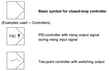
Additional symbols are used as a result of the displays (outputs), which are also located in the process control console.

The following symbols are used to represent the binary control systems, which are also required to automate process technology operations.

This set of symbols covers all the important automation equipment to be recorded in the EMCS block diagrams.
Finally, appropriate symbols also have to be used for the connection of of this automation equipment to identify the corresponding transmission lines in accordance with DIN 19227/ DIN 19227/Part 2.
One concluding consideration of significance for the immediate preparation of these EMCS block diagrams, arises from the question concerning the type of hardware used for automation equipment. The following should be noted in this context:
>> The proposed symbols for sensors and actuators are to be used independently of the basic hardware used (e. g. size, constructional design, etc.).
>> The symbols you are now familiar with are modified as follows for the equally essential processor and display technology, as well as the measuring transducers and binary control system, which can also be realised, e.g. in a process control system, by means of software functions:

As already indicated, the preliminary EMCS block diagram connects the automation equipment required for the configuration of EMCS points. The small-scale installation is used as an example to set out the preliminary EMCS block diagram for the filling level closed control loop (Picture 1).
To this end, the following have been configured, based on the structure of an automation system: Sensors and actuators at the field level; measuring transducers in the switchroom, plus for instance also a compact controller (PLC technology), and the operating and monitoring computer in the process control console. In parallel with the preliminary EMCS block diagram, the so-called Equipment list (Table shown on Picture 2) is prepared.

Picture 2: Equipment list for filling level closed control loop (LIC 30)
This list is drawn up for each EMCS point and in that order contains the automation equipment for sensor, actuator, transducer and processor technologies with precise designation so that, apart from the purpose of documentation, it also contains the necessary ordering information. In addition, the so-called allocation lists are also prepared on the basis of the preliminary EMCS block diagrams. The allocation lists are geared to the container systems used in the automation system and as such provide the assembly specification for the attachment of the automation equipment deployed (Picture 3). In this context it should be noted that the container systems used are subdivided into assembly levels and these again into assembly positions. The allocation list is therefore a clearly arranged document used directly for the assembly of the automation equipment.

Picture 3: Allocation list – Basic configuration
No comments:
Post a Comment