In practice, process technology, as on the small-scale experimental modules, an automation system, apart from the field instrumentation (sensors/actuators), is dominated by process control and instrumentation technology. These tools for automation are fitted into a basic structure of the automation system, which is universally accepted as a means of reference. This basic configuration comprises the typical components process control console, switchroom and fieldlevel (Picture 1) and clearly sets out the use of the tools for automation, which are important as far as project design is concerned.
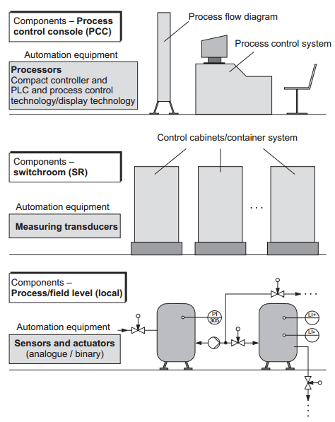
Picture 1: Basic structure of an automation system
According to this, it is possible to proceed on the assumption of the following allocation:
>> Process control console ⇒ Processor technology / PLC technology
>> Switchroom ⇒ Measuring transducer technology
>> Process / Field level ⇒ Sensors / Actuators and measuring transducer technology
By recollecting the basic configuration of the single-loop control loop and the binary control system (Picture 2) in this conjunction, it is also possible allocate these in the basic configuration with the help of the automation tools used. This also works for the simple measuring chain (separate measuring point). Finally, it is crucial to define all the EMCS points (electronic measuring and control points) required for the solution of an automation task. As already established, the tender specification or customer’s invitation to tender is generally available for this, on the basis of which the designer (contractor) can draw up the specification.

Picture 2: Automation equipment of a single-loop closed control loop and the binary control system
Tender specification – performance specification
VDI/VDE 3694 formally specifies that the tender specification or performance specification forms the basis of any automation project, i.e. according to VDI/VDE.
The tender specification contains the requirements from the user’s viewpoint, including all parameter conditions "The tender specification defines, WHAT is to be solved and the PURPOSE of the solution ". (The tender specification is drawn up by the customer or commissioned by him. It acts as a basis for the invitation to bid, the quotation and/or contract basis.)
The performance specification contains the tender specification and also details the user tasks and, enlarging on the tender specification, describes the implementation requirements, taking into consideration concrete solution approaches. "The performance specification defines HOW and WITH WHAT the requirements are to be implemented." (The performance specification is generally drawn up by the contractor in cooperation with the customer once the order has been placed.)
In industrial practice, reference is almost always made to the invitation to tender again, which also defines the process technology and the corresponding automation tasks, although generally not to the extent and depth required for the tender specifications as specified in VDI/VDE 3694. It is therefore essential for the contractor (project designer) to give maximum consideration to the planning and calculation of his quotation (performance specification), i.e. contents, size and costs of the automation project to be realised. For a tried and tested practical approach, the project design engineer should therefore start with an analysis and the functional sequence of the respective process technology (evaluation of the process flow diagram, including the corresponding process description).
The process flow diagram for continuous processes is drawn up according to DIN 28004 guidelines and is the diagrammatic representation of the piping and devices. An attached description and additional entries of process parameters in the process flow diagram complete the initial general documentation of the process technology and automation tasks. As such, it becomes necessary to define in detail the automation tasks (EMCS points). This is done by entering the EMCS points in the process flow diagram, i.e. the process flow diagram becomes the PI flow diagram.
The PI flow diagram is therefore the first concrete project step, which defines the number and function of the required EMCS points.
No comments:
Post a Comment