Pages

3PE Systems Calculator


Electro-Magnetic World and BMG Universe created simple, but very useful tool for electrical engineers, a 3PE Calculator. This program provides the basic information for design and configuration of 3-phase electrical (3PE) systems. Depending on power consumption of the consumer (EM motor), the program provides information for selecting proper cable, fuses, current transformer (CT) for measurement purposes, contactors for operating with the load and motor protectors for over-current protection of the motors.


3PE Systems Calculator 1.0 is program that provides useful information for designing and implementation of 3PE Systems. The calculations are made for 3-phase asynchronous EM motors as consumers in the systems, but they can also be used and for any other type of 3-phase load consumer.


IMPORTANT NOTE: This program only provides useful information for creating and design of the 3PE systems. The calculations and predictions that are made here are clearly highlighted, and if you make any kind of mistake in your design using this program we take NO RESPONSIBILITY at all !

______________________________


About System A


System A is 3PE system for direct start of 3-phase asynchronous EM motors (4-pole). Also, there is an option for forward-reverse mode of operation of the EM motors. The one-pole schematic of the system A is shown on Picture 1. In case of forward-reverse mode of operation, instead of contactor C1, the both contactors C1 and C2 are in use, as is shown on the one-pole schematic of the System A. The contactors C1 and C2 are of the same type.


Picture 1: 3PE System A - One-pole schematic


There are 30 standard values for nominal power of EM motor, starting from 0.18 kW up to 200 kW. You can choose each one of them, and the program will provide proper information for the parameters you need for design and implementation of the selected System A.

The section of the cables is approximately calculated for the voltage drop less than 2% up to 80 meters distance (from the connection to the consumer).


Note: For direct start of the EM motor, it's consider that the peak current at the start up is about 6 times greater than the nominal current of the EM motor (Ip = 6*In). The time required for the motor to achieve its momentum is about 5 seconds (tm = 5s).


Important!

For more precise calculations for the section of the cable depending on the allowed voltage drop for the given distance and the control of the heating of the cable you need to choose the proper formulas to recalculate this.


About System B


System B is a 3PE system for star-delta (Y-D) starting of 3-phase asynchronous EM motors (4-pole), or using the soft starter or frequency regulator for starting the motor. In this system there are 3 contactors in use, as is shown on the one-pole schematic of the System B on Picture 2. The contactor C1 brings the 3 phases to the motor. The contactor C2 creates delta connection of the motor, and the contactor C3 creates star connection. The contactors C1 and C2 are the same type, and contactor C3 can be the same type or one class lower from C1 and C2, because the current in that circuit is lower.


Picture 2: 3PE System B - One-pole schematic


There are 30 standard values for nominal power of EM motor, starting from 0.55 kW up to 355 kW. You can choose each one of them, and the program will provide proper information for the parameters you need for design and implementation of the selected System B.

The section of the cables is approximately calculated for the voltage drop less than 2% up to 80 meters distance (from the connection to the consumer).


Note: For star - delta starting of the EM motor, it's consider that the peak current at the start up is about 2 times greater than the nominal current of the EM motor (Ip = 2*In). The time required for the motor to achieve its momentum is about 15 seconds (tm = 15s). And also, here is important to have "dead time" between the star and delta connection. That means that when the star connection is switch off, the motor should have no voltage for short time interval (dead time) before the delta connection is switched on. This dead time is about 100 miliseconds (td = 100 ms), and is easy to achieve with proper time relay.


Important!

For more precise calculations for the section of the cable depending on the allowed voltage drop for the given distance and the control of the heating of the cable you need to choose the proper formulas to recalculate this.


Info for the manufacturers


There are 2 manufacturers for contactors and motor protectors used in this program:


>> RADE KONCAR

The KONCAR contactors used in this program are CNM series contactors, and the motor protectors (thermal overload relays) are TRM series relays from KONCAR. You can find more information on KONCAR's site: Rade KONCAR


>> SIEMENS

The Siemens contactors used in this program are 3RT series contactors, and the motor protectors are 3RV Siemens Sirius Motor starter protectors series. You can find more information on Siemens's site: Siemens


Free Download of 3PE Calculator Android version


Finaly, this simple and useful tool can be downloaded for free on the Google Play store: 3PE Systems Calculator 1.0

Motors Mounting


NEMA Dimensions


NEMA has standardized motor dimensions for a range of frame sizes. Standardized dimensions include bolt hole size, mounting base dimensions, shaft height, shaft diameter, and shaft length. Use of standardized dimensions allows existing motors to be replaced without reworking the mounting arrangement. In addition, new installations are easier to design because the dimensions are known. Standardized dimensions include letters to indicate the dimension’s relationship to the motor. For example, the letter C indicates the overall length of the motor and the letter E represents the distance from the center of the shaft to the center of the mounting holes in the feet (Picture 1). Dimensions are found by referring to a table in the motor data sheet and referencing the letter to find the desired dimension.


Picture 1: Motor dimensions


NEMA divides standard frame sizes into two categories, fractional horsepower and integral horsepower. The most common frame sizes for fractional horsepower motors are 42, 48, and 56. Integral horsepower motors are designated by frame sizes 143 and above. A T in the motor frame size designation for an integral horsepower motor indicates that the motor is built to current NEMA frame standards. Motors that have a U in their motor frame size designation, are built to NEMA standards that were in place between 1952 and 1964.

The frame size designation is a code to help identify key frame dimensions. The first two digits are used to determine the shaft height. The shaft height is the distance from the center of the shaft to the mounting surface. To calculate the shaft height, divide the first two digits of the frame size by 4. For example, a 143T frame size motor (Picture 2) has a shaft height of 3½ inches (14 ÷ 4).


Picture 2: 143T frame size motor


The third digit in the integral T frame size number is the NEMA code for the distance between the center lines of the motor feet mounting bolt holes. The distance is determined by matching this digit with a table in NEMA publication MG-1 (Picture 4). For example, the distance between the center lines of the mounting bolt holes in the feet of a 143T frame is 4.00 inches (Picture 3).


Picture 3: Distance between the bolt holes


Picture 4: Distance between the bolt holes table


IEC Dimensions


IEC also has standardized dimensions, but these dimensions differ from NEMA standards. An example of the IEC dimensions are shown in the following drawing on Picture 5.


Picture 5: IEC Dimensions


Mounting Positions


The typical floor mounting positions are illustrated in the following drawing on Picture 6, and are referred to as F-1 and F-2 mountings. The conduit box can be located on either side of the frame to match the mounting arrangement and position. The standard location of the conduit box is on the left-hand side of the motor when viewed from the shaft end. This is referred to as the F-1 mounting. The conduit opening can be placed on any of the four sides of the box by rotating the box in 90° steps.


Picture 6: F-1 and F-2 mountings


With modification, a foot-mounted motor can be mounted on a wall and ceiling. Typical wall and ceiling mounts are shown in the following illustration on Picture 7. Wall mounting positions have the prefix W and ceiling mounted positions have the prefix C.


Picture 7: Typical wall and ceiling mounts (W & C)


Mounting Faces


It is sometimes necessary to connect the motor directly to the equipment it drives. In the following example (Picture 8) a motor is connected directly to a gear box.


Picture 8: Motor connected to a gear box


C-face Motor


The face, or the end, of a C-face motor has threaded bolt holes. Bolts to mount the motor pass through mating holes in the equipment and into the face of the motor (Picture 9).


Picture 9: C-face motor


D-flange Motor


The bolts go through the holes in the flange of a D-flange motor and into threaded mating holes of the equipment (Picture 10).


Picture 10: D-flange motor

Motor Enclosures


A motor’s enclosure not only holds the motors components together, it also protects the internal components from moisture and containments. The degree of protection depends on the enclosure type. In addition, the type of enclosure affects the motor’s cooling. There are two categories of enclosures: open and totally enclosed.


Open Drip Proof (ODP) Enclosure


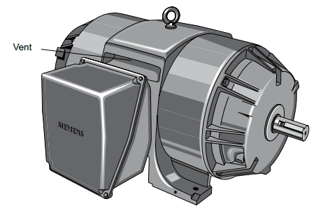
Open enclosures permit cooling air to flow through the motor. One type of open enclosure is the open drip proof (ODP) enclosure (Picture 1). This enclosure has vents that allow for air flow. Fan blades attached to the rotor move air through the motor when the rotor is turning. The vents are positioned so that liquids and solids falling from above at angles up to 15° from vertical cannot enter the interior of the motor when the motor is mounted on a horizontal surface. When the motor is mounted on a vertical surface, such as a wall or panel, a special cover may be needed. ODP enclosures should be used in environments free from contaminates.


Picture 1: ODP Enclosure


Totally Enclosed Non-Ventilated (TENV) Enclosure


In some applications, the air surrounding the motor contains corrosive or harmful elements which can damage the internal parts of a motor. A totally enclosed non-ventilated (TENV) motor enclosure limits the flow of air into the motor, but is not airtight (Picture 2). However, a seal at the point where the shaft passes through the housing prevents water, dust, and other foreign matter from entering the motor along the shaft. Most TENV motors are fractional horsepower. However, integral horsepower TENV motors are used for special applications. The absence of ventilating openings means that all the heat from inside the motor must dissipate through the enclosure by conduction. These larger horsepower TENV motors have an enclosure that is heavily ribbed to help dissipate heat more quickly. TENV motors can be used indoors or outdoors.


Picture 2: TENV Enclosure


Totally Enclosed Fan Cooled (TEFC) Enclosure


A totally enclosed fan-cooled (TEFC) motor is similar to a TENV motor, but has an external fan mounted opposite the drive end of the motor (Picture 3). The fan blows air over the motor’s exterior for additional cooling. The fan is covered by a shroud to prevent anyone from touching it. TEFC motors can be used in dirty, moist, or mildly corrosive environments.


Picture 3: TEFC Enclosure


Explosion Proof (XP)


Hazardous duty applications are commonly found in chemical processing, mining, foundry, pulp and paper, waste management, and petrochemical industries. In these applications, motors have to comply with the strictest safety standards for the protection of life, machines and the environment. This often requires use of explosion proof (XP) motors. An XP motor is similar in appearance to a TEFC motor, however, most XP enclosures are cast iron (Picture 4). In the United States, the application of motors in hazardous locations is subject to National Electrical Code® and standards set by Underwriters Laboratories and various regulatory agencies.


Picture 4: XP Enclosure


Hazardous (Classified) Locations


You should never specify or suggest the type of hazardous location classification, it is the user’s responsibility to comply with all applicable codes and to contact local regulatory agencies to define hazardous locations. Refer to the National Electrical Code®Article 500 for additional information.


Division I and II Locations


Division I locations normally have hazardous materials present in the atmosphere. Division II locations may have hazardous material present in the atmosphere under abnormal conditions.


Classes and Groups


Locations defined as hazardous, are further defined by the class and group of hazard. For example, Class I, Groups A through D have gases or vapors present. Class II, Groups E, F, and G have flammable dust, such as coke or grain dust. Class III is not divided into groups. This class involves ignitable fibers and lints (Picture 5).


Picture 5: Classes and Groups table

Matching Motors to the Load


One way to evaluate whether the torque capabilities of a motor meet the torque requirements of the load is to compare the motor’s speed-torque curve with the speed-torque requirements of the load (Picture 1).


Picture 1: Speed-torque curve of the motor and speed-torque requirements of the load


Load Characteristics Tables


A table, like one shown on Picture 2 below, can be used to find the load torque characteristics. NEMA publication MG 1 is one source of typical torque characteristics.


Picture 2: Load torque characteristics table (example)


Calculating Load Torque


The most accurate way to obtain torque characteristics of a given load is from the equipment manufacturer. However, the following procedure illustrates how load torque can be determined. The following illustration on Picture 3 shows a pulley fastened to the shaft of a load. A cord is wrapped around the pulley with one end connected to a spring scale. Pull on the scale until the shaft turns and note the force reading on the scale. Then, multiply the force required to turn the shaft by the radius of the pulley to calculate the torque value. Keep in mind that the radius is measured from the center of the shaft.


Picture 3: Load torque measurement


For example, if the radius of the pulley is 1 foot and the force required to turn the shaft is 10 pounds, the torque requirement is 10 lb-ft. Remember that this is just the required starting torque. The amount of torque required to turn the load can vary with speed. At any point on the speed-torque curve, the amount of torque produced by a motor must always at least equal the torque required by its load. If the motor cannot produce sufficient torque, it will either fail to start the load, stall, or run in an overloaded condition. This will probably cause protective devices to trip and remove the motor from the power source.


Centrifugal Pump


In the following example (Picture 4), a centrifugal pump requires a full-load torque of 600 lb-ft. This pump only needs approximately 20% of full-load torque to start. The required torque dips slightly as the load begins to accelerate and then increases to full-load torque as the pump comes up to speed. This is an example of a variable torque load.


Picture 4: Speed-torque curve for centrifugal pump


The motor selected in this example is a NEMA B motor that is matched to the load. In other words, motor has sufficient torque to accelerate the load to rated speed.


Screw Down Actuator


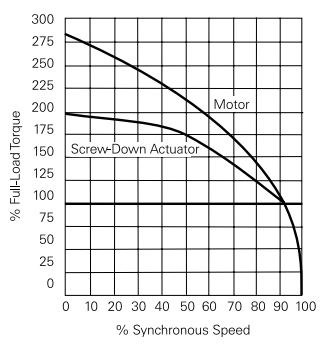
In the following example (Picture 5), the load is a screw down actuator with a starting torque equal to 200% of full-load torque. Note that the NEMA B motor chosen for this example does not provide sufficient torque to start the load.


Picture 5: Speed-torque curve for screw down actuator


One solution to this problem is to use a higher horsepower NEMA B motor. A less expensive solution might be to use a NEMA D motor which has higher starting torque for the same horsepower rating (Picture 6).


Picture 6: Speed-torque curve of motor sufficient for screw down actuator

AC Motors and AC Drives


Many applications require the speed of an AC motor to vary. The easiest way to vary the speed of an AC induction motor is to use an AC drive to vary the applied frequency. Operating a motor at other than the rated frequency and voltage affect both motor current and torque.


Volts per Hertz (V/Hz) Ratio


The volts per hertz (V/Hz) ratio is the ratio of applied voltage to applied frequency for a motor. 460 VAC is the most common voltage rating for an industrial AC motor manufactured for use in the United States. These motors have a frequency rating of 60Hz. This provides a V/Hz ratio of 7.67. Not every motor has a 7.67 V/Hz ratio. A 230 Volt, 60 Hz motor, for example, has a 3.8 V/Hz ratio.


Constant Torque Operation


AC motors running on an AC line operate with a constant flux because voltage and frequency are constant. Motors operated with constant flux are said to have constant torque. Actual torque produced, however, is dependent upon the load. An AC drive is capable of operating a motor with constant flux from approximately 0 Hz to the motor’s rated nameplate frequency (typically 60 Hz). This is the constant torque range. As long as a constant volts per hertz ratio is maintained the motor will have constant torque characteristics.

The following graphs shown on Picture 1 illustrate the constant volts per hertz ratio of a 460 volt, 60 Hz motor and a 230 volt, 60 Hz motor operated over the constant torque range. Keep in mind that if the applied frequency increases, stator reactance increases. In order to compensate for this, the drive must simultaneously increase voltage proportionally. Otherwise, stator current, flux, and torque would decrease.


Picture 1: Volts per Hertz ratio graphs


Constant Horsepower


Some applications require the motor to be operated above base speed. Because applied voltage must not exceed the rated nameplate voltage, torque decreases as speed increases. This is referred to as the constant horsepower range because any change in torque is compensated by the opposite change in speed.

Power[HP] = (Torque[lb-ft] x Speed[RPM]) / 5252

If the motor is operated in both the constant torque and constant horsepower ranges, constant volts per hertz and torque are maintained up to 60 Hz. Above 60 Hz, the volts per hertz ratio decreases, with a corresponding decrease in torque (Picture 2).


Picture 2: Volts per Hertz ratio decreases above the main operating frequency


Reduced Voltage and Frequency Starting


Recall that when a NEMA B motor is started at full voltage, it develops approximately 150% starting torque and 600% starting current. When the motor is controlled by an AC drive, the motor is started at reduced voltage and frequency. For example, the motor may start with approximately 150% torque, but only 150% of full load current. As the motor is brought up to speed, voltage and frequency are increased, and this has the effect of shifting the motor’s speed-torque curve to the right. The dotted lines on the following speed-torque curve represent the portion of the curve not used by the drive (Picture 3). The drive starts and accelerates the motor smoothly as frequency and voltage are gradually increased to the desired speed.


Picture 3: Speed-Torque curve


Some applications require higher than 150% starting torque. A conveyor, for example, may require 200% rated torque for starting. This is possible if the drive and motor are appropriately sized.


Selecting a Motor


AC drives often have more capability than the motor. Drives can run at higher frequencies than may be suitable for an application. In addition, drives can run at speeds too low for self-cooled motors to develop sufficient air flow. Each motor must be evaluated according to its own capability before selecting it for use on an AC drive.
Harmonics, voltage spikes, and voltage rise times of AC drives are not identical. Some AC drives have more sophisticated filters and other components designed to minimize undesirable heating and insulation damage to the motor. This must be considered when selecting an AC drive/motor combination.


Distance Between the Drive and the Motor


Distance from the drive to the motor must also be taken into consideration. All motor cables have line-to-line and line-to-ground capacitance. The longer the cable, the greater the capacitance. Some types of cables, such as shielded cable or cables in metal conduit, have greater capacitance. Spikes occur on the output of AC drives because of the charging current in the cable capacitance. Higher voltage (460 VAC) and higher capacitance (long cables) result in higher current spikes. Voltage spikes caused by long cable lengths can potentially shorten the life of the AC drive and motor.

Service Factor on AC Drives


A high efficiency motor with a 1.15 service factor is recommended when used with an AC drive. Due to heat associated with harmonics of an AC drive, the 1.15 service factor is reduced to 1.0.

Derating Factors for AC Motors


Several factors can affect the performance of an AC motor. These must be considered when applying a motor.


Voltage Variation


As previously discussed, AC motors have a rated voltage and frequency. Some motors have connections for more that one rated voltage. The following table on Picture 1 shows the most common voltage ratings for NEMA motors.


Picture 1: Standardized voltages and frequencies


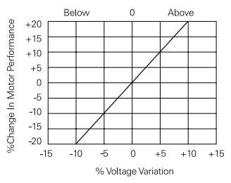
A small variation in supply voltage can have a dramatic affect on motor performance. In the following chart shown on Picture 2, for example, when voltage is 10% below the rated voltage of the motor, the motor has 20% less starting torque. This reduced voltage may prevent the motor from getting its load started or keeping it running at rated speed. A 10% increase in supply voltage, on the other hand, increases the starting torque by 20%. This increased torque may cause damage during startup. A conveyor, for example, may lurch forward at startup. A voltage variation also causes similar changes in the motor’s starting and full-load currents and temperature rise.


Picture 2: Change in motor performance with voltage variation


Frequency


A variation in the frequency at which the motor operates causes changes primarily in speed and torque characteristics. A 5% increase in frequency, for example, causes a 5% increase in full-load speed and a 10% decrease in torque (Picture 3).


Picture 3: Frequency variation effects


Altitude


Standard motors are designed to operate below 3300 feet. Air is thinner, and heat is not dissipated as quickly above 3300 feet. Most motors must be derated for altitudes above 3300 feet. The following chart on Picture 4 shows typical horsepower derating factors, but the derating factor should be checked for each motor. A 50 HP motor operated at 6000 feet, for example, would be derated to 47 HP, providing the 40°C ambient rating is still required.


Picture 4: Altitude derating factor


Ambient Temperature


The ambient temperature may also have to be considered. The ambient temperature requirement may be reduced from 40°C to 30°C at 6600 feet on many motors. However, a motor with a higher insulation class may not require derating in these conditions (Picture 5).


Picture 5: Ambient temperature reduces with altitude


NEMA Motor Characteristics


Standard Motor Designs


Motors are designed with speed-torque characteristics to match the requirements of common applications. The four standard NEMA motor designs, A, B, C, and D, have different characteristics. This article provides descriptions for each of these motor designs with emphasis on NEMA design B, the most common three-phase AC induction motor design.


Speed-Torque Curve for NEMA B Motor


Because motor torque varies with speed, the relationship between speed and torque is often shown in a graph, called a speed-torque curve. This curve shows the motor’s torque, as a percentage of full-load torque, over the motor’s full speed range, shown as a percentage of its synchronous speed. The following speed-torque curve shown on Picture 1 is for a NEMA B motor. NEMA B motors are general purpose, single speed motors suited for applications that require normal starting and running torque, such as fans, pumps, lightly-loaded conveyors, and machine tools. Using a 30 HP, 1765 RPM NEMA B motor as an example, full-load torque can be calculated by transposing the formula for horsepower:

HP = (Torque[lb-ft] x Speed[RPM])/5252 => Torque = 89.3 lb-ft


Picture 1: NEMA B Motor speed-torque curve


Starting Torque


Starting torque, also referred to as locked rotor torque, is the torque that the motor develops each time it is started at rated voltage and frequency. When voltage is initially applied to the motor’s stator, there is an instant before the rotor turns. At this instant, a NEMA B motor develops a torque approximately equal to 150% of full-load torque. For the 30 HP, 1765 RPM motor used in this example, that’s equal to 134.0 lb-ft of torque (Picture 2).


Picture 2: Starting torque


Pull-up Torque


As the motor picks up speed, torque decreases slightly until point B on the graph is reached (Picture 3). The torque available at this point is called pull-up torque. For a NEMA B motor, this is slightly lower than starting torque, but greater than full-load torque.


Breakdown Torque


As speed continues to increase from point B to point C (see Picture 3), torque increases up to a maximum value at approximately 200% of full-load torque. This maximum value of torque is referred to as breakdown torque. The 30 HP motor in this example has a breakdown torque of approximately 178.6 lb-ft.


Picture 3: Pull-up and Breakdown torque


Full-Load Torque


Torque decreases rapidly as speed increases beyond breakdown torque until it reaches full-load torque at a speed slightly less than 100% of synchronous speed (Picture 4). Full-load torque is developed with the motor operating at rated voltage, frequency, and load. The motor in this example has a synchronous speed of 1800 RPM and a full-load speed of 1765 RPM. Therefore, its slip is 1.9%.


Picture 4: Full-load torque


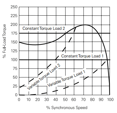
Speed-torque curves are useful for understanding motor performance under load. The following speed-torque curve on Picture 5 shows four load examples. This motor is appropriately sized for constant torque load 1 and variable torque load 1. In each case, the motor will accelerate to its rated speed. With constant torque load 2, the motor does not have sufficient starting torque to turn the rotor. With variable torque load 2, the motor cannot reach rated speed. In these last two examples, the motor will most likely overheat until its overload relay trips.


Picture 5: Constant and variable torque loads


Starting Current and Full-Load Current


Starting current, also referred to as locked rotor current, is the current supplied to the motor when the rated voltage is initially applied with the rotor at rest (Picture 6). Full-load current is the current supplied to the motor with the rated voltage, frequency, and load applied and the rotor up to speed. For a NEMA B motor, starting current is typically 600-650% of full-load current. Knowledge of the current requirements for a motor is critical for the proper application of over-current protection devices.


Picture 6: Starting and Full-load current


NEMA A Motor


NEMA A motors are the least common design. NEMA A motors have a speed-torque curve similar to that of a NEMA B motor, but typically have higher starting current. As a result, overcurrent protection devices must be sized to handle the increased current. NEMA A motors are typically used in the same types of applications as NEMA B motors.


NEMA C Motor


NEMA C motors are designed for applications that require a high starting torque for hard to start loads, such as heavily-loaded conveyors, crushers and mixers. Despite the high starting torque, these motors have relatively low starting current. Slip and full-load torque are about the same as for a NEMA B motor. NEMA C motors are typically single speed motors which range in size from approximately 5 to 200 HP. The following speed-torque curve shown on Picture 7 is for a 30 HP NEMA C motor with a full-load speed of 1765 RPM and a full-load torque of 89.3 lb-ft. In this example, the motor has a starting torque of 214.3 lb-ft, 240% of full-load torque and a breakdown torque of 174 lb-ft.


Picture 7: NEMA C Motor speed-torque curve


NEMA D Motor


The starting torque of a NEMA design D motor is approximately 280% of the motor’s full-load torque. This makes it appropriate for very hard to start applications such as punch presses and oil well pumps. NEMA D motors have no true breakdown torque. After starting, torque decreases until full-load torque is reached. Slip for NEMA D motors ranges from 5 to 13%.
The following speed torque curve shown on Picture 8 is for a 30 HP NEMA D motor with a full-load speed of 1656 RPM and a full load torque of 95.1 lb-ft. This motor develops approximately 266.3 lb-ft of starting torque.


Picture 8: NEMA D Motor speed-torque curve

Motor Specifications


Nameplate


The nameplate of a motor provides important information necessary for proper application. For example, the following illustration on Picture 1 shows the nameplate of a 30 horsepower (HP) three-phase (3 PH) AC motor. The following paragraphs explain some of the other nameplate information for this motor.


Picture 1: Nameplate of motor (example)


Voltage Source (VOLTS) and Full-load Current (AMPS)


AC motors are designed to operate at standard voltages. This motor is designed to be powered by a three-phase 460 V supply. Its rated full-load current is 35.0 A.


Base Speed (RPM) and Frequency (HERTZ)


Base speed is the speed, given in RPM, at which the motor develops rated horsepower at rated voltage and frequency. Base speed is an indication of how fast the output shaft will turn the connected equipment when fully loaded. This motor has a base speed of 1775 RPM at a rated frequency of 60 Hz. Because the synchronous speed of a 4-pole motor operated at 60 Hz is 1800 RPM, the full-load slip in this case is 1.4%. If the motor is operated at less than full load, the output speed will be slightly greater than the base speed.


Service Factor


Service factor is a number that is multiplied by the rated horsepower of the motor to determine the horsepower at which the motor can be operated. Therefore, a motor designed to operate at or below its nameplate horsepower rating has a service factor of 1.0.
Some motors are designed for a service factor higher than 1.0, so that they can, at times, exceed their rated horsepower For example, this motor has a service factor of 1.15. A 1.15 service factor motor can be operated 15% higher than its nameplate horsepower. Therefore this 30 HP motor can be operated at 34.5 HP. Keep in mind that any motor operating continuously above its rated horsepower will have a reduced service life.


Insulation Class


NEMA defines motor insulation classes to describe the ability of motor insulation to handle heat. The four insulation classes are A, B, F, and H. All four classes identify the allowable temperature rise from an ambient temperature of 40° C (104° F). Classes B and F are the most commonly used. Ambient temperature is the temperature of the surrounding air. This is also the temperature of the motor windings before starting the motor, assuming the motor has been stopped long enough. Temperature rises in the motor windings as soon as the motor is started. The combination of ambient temperature and allowed temperature rise equals the maximum rated winding temperature. If the motor is operated at a higher winding temperature, service life will be reduced. A 10° C increase in the operating temperature above the allowed maximum can cut the motor’s insulation life expectancy in half. The following illustration on Picture 2 shows the allowable temperature rise for motors operated at a 1.0 service factor at altitudes no higher than 3300 ft. Each insulation class has a margin allowed to compensate for the motor’s hot spot, a point at the center of the motor’s windings where the temperature is higher. For motors with a service factor of 1.15, add 10° C to the allowed temperature rise for each motor insulation class.


Picture 2: The allowable temperature rise for motors per class, operated at a 1.0 service factor
The motor in this example has insulation class F and a service factor of 1.15. This means that its winding temperature is allowed to rise to 155° C with an additional 10° C hot spot allowance.


NEMA Motor Design


NEMA also uses letters (A, B, C, and D) to identify motor designs based on torque characteristics. The motor in this example is a design B motor, the most common type. Motor design A is the least common type.


Motor Efficiency


Motor efficiency is a subject of increasing importance, especially for AC motors. AC motor efficiency is important because AC motors are widely used and account for a significant percentage of the energy used in industrial facilities. Motor efficiency is the percentage of the energy supplied to the motor that is converted into mechanical energy at the motor’s shaft when the motor is continuously operating at full load with the rated voltage applied. Because motor efficiencies can vary among motors of the same design, the NEMA nominal efficiency percentage on the nameplate is representative of the average efficiency for a large number of motors of the same type. The motor in this example has a NEMA nominal efficiency of 93.6%.
Both NEMA and the Energy Policy Act of 1992 (EPAct) specify the same process for testing motor efficiency. In 2001, NEMA established the NEMA Premium designation for three-phase AC motors that meet even higher efficiency standards than required by EPAct. More recently, the Energy Independence and Security Act of 2007 (EISA) was passed. EISA requires most motors manufactured after December 19, 2010 to meet NEMA Premium efficiency levels. This includes motors previously covered by EPAct and some additional categories of motors.
Siemens NEMA Premium Efficient motors meet NEMA Premium efficiency standards and Siemens Ultra Efficient motors with exclusive die cast copper rotor technology exceed NEMA Premium efficiency standards.

Rotor Rotation


Permanent Magnet


To see how a rotor works, a magnet mounted on a shaft can be substituted for the squirrel cage rotor. When the stator windings are energized, a rotating magnetic field is established. The magnet has its own magnetic field that interacts with the rotating magnetic field of the stator. The north pole of the rotating magnetic field attracts the south pole of the magnet, and the south pole of the rotating magnetic field attracts the north pole of the magnet (Picture 1). As the magnetic field rotates, it pulls the magnet along. AC motors that use a permanent magnet for a rotor are referred to as permanent magnet synchronous motors. The term synchronous means that the rotors rotation is synchronized with the magnetic field, and the rotor’s speed is the same as the motor’s synchronous speed.


Picture 1: The rotating magnetic field of the stator


Induced Voltage Electromagnet


Instead of a permanent magnet rotor, a squirrel cage induction motor induces a current in its rotor, creating an electromagnet. As the following illustration on Picture 2 shows, when current is flowing in a stator winding, the electromagnetic field created cuts across the nearest rotor bars.


Picture 2: Rotor as electromagnet


When a conductor, such as a rotor bar, passes through a magnetic field, a voltage (emf) is induced in the conductor. The induced voltage causes current flow in the conductor. In a squirrel cage rotor, current flows through the rotor bars and around the end ring and produces a magnetic field around each rotor bar. Because the stator windings are connected to an AC source, the current induced in the rotor bars continuously changes and the squirrel cage rotor becomes an electromagnet with alternating north and south poles (Picture 3).


Picture 3: Squirrel cage rotor as electromagnet


The following illustration on Picture 4 shows an instant when winding A1 is a north pole and its field strength is increasing. The expanding field cuts across an adjacent rotor bar, inducing a voltage. The resultant current flow in one rotor bar produces a south pole. This causes the motor to rotate towards the A1 winding. At any given point in time, the magnetic fields for the stator windings are exerting forces of attraction and repulsion against the various rotor bars. This causes the rotor to rotate, but not exactly at the motor’s synchronous speed.


Picture 4: Rotation of the motor


Slip


For a three-phase AC induction motor, the rotating magnetic field must rotate faster than the rotor to induce current in the rotor. When power is first applied to the motor with the rotor stopped, this difference in speed is at its maximum and a large amount of current is induced in the rotor. After the motor has been running long enough to get up to operating speed, the difference between the synchronous speed of the rotating magnetic field and the rotor speed is much smaller. This speed difference is called slip. Slip is necessary to produce torque. Slip is also dependent on load. An increase in load causes the rotor to slow down, increasing slip. A decrease in load causes the rotor to speed up, decreasing slip. Slip is expressed as a percentage and can be calculated using the following formula:

% Slip = (NS - NR)/NS x 100

For example, a four-pole motor operated at 60 Hz has a synchronous speed (NS) of 1800 RPM. If its rotor speed (NR) at full load is 1775 RPM, then its full load slip is 1.4%.


Wound Rotor Motor


The discussion to this point has been centered on the more common squirrel cage rotor. Another type of three-phase induction motor is the wound rotor motor. A major difference between the wound rotor motor and the squirrel cage rotor is that the conductors of the wound rotor consist of wound coils instead of bars. These coils are connected through slip rings and brushes to external variable resistors (Picture 5). The rotating magnetic field induces a voltage in the rotor windings. Increasing the resistance of the rotor windings causes less current to flow in the rotor windings, decreasing rotor speed. Decreasing the resistance causes more current to flow, increasing rotor speed.


Picture 5: Wound rotor motor


Synchronous Motor


Another type of three-phase AC motor is the synchronous motor. The synchronous motor is not an induction motor. One type of synchronous motor is constructed somewhat like a squirrel cage rotor. In addition to rotor bars, coil windings are also used. The coil windings are connected to an external DC power supply by slip rings and brushes (Picture 6). When the motor is started, AC power is applied to the stator, and the synchronous motor starts like a squirrel cage rotor. DC power is applied to the rotor coils after the motor has accelerated. This produces a strong constant magnetic field in the rotor which locks the rotor in step with the rotating magnetic field. The rotor therefore turns at synchronous speed, which is why this is a synchronous motor. As previously mentioned, some synchronous motors use a permanent magnet rotor. This type of motor does not need a DC power source to magnetize the rotor.


Picture 6: Synchronous motor

Developing a Rotating Magnetic Field


The principles of electromagnetism explain the shaft rotation of an AC motor. Recall that the stator of an AC motor is a hollow cylinder in which coils of insulated wire are inserted (Picture 1).


Picture 1: Stator of AC motor


Stator Coil Arrangement


The following diagram on Picture 2 shows the electrical configuration of stator windings. In this example, six windings are used, two for each of the three phases. The coils are wound around the soft iron core material of the stator. When current is applied, each winding becomes an electromagnet, with the two windings for each phase operating as the opposite ends of one magnet. In other words, the coils for each phase are wound in such a way that, when current is flowing, one winding is a north pole and the other is a south pole. For example, when A1 is a north pole, A2 is a south pole and, when current reverses direction, the polarities of the windings also reverse.


Picture 2: Stator coil configuration


Stator Power Source


The stator is connected to a three-phase AC power source. The following illustration on Picture 3 shows windings A1 and A2 connected to phase A of the power supply. When the connections are completed, B1 and B2 will be connected to phase B, and C1 and C2 will be connected to phase C.


Picture 3: Stator connected to phase A of a three-phase source


As the following illustration shows, coils A1, B1, and C1 are 120° apart. Note that windings A2, B2, and C2 also are 120° apart. This corresponds to the 120° separation between each electrical phase. Because each phase winding has two poles, this is called a two-pole stator (Picture 4).


Picture 4: 2-pole stator windings


When AC voltage is applied to the stator, the magnetic field developed in a set of phase coils depends on the direction of current flow. Refer to the following chart shown on Picture 5 as you read the explanation of how a rotating magnetic field is developed. This chart assumes that a positive current flow in the A1, B1 or C1 windings results in a north pole.


Picture 5: Current flow direction chart


Start


In the following illustration shown on Picture 6, a start time has been selected during which phase A has no current flow and its associated coils have no magnetic field. Phase B has current flow in the negative direction and phase C has current flow in the positive direction. Based on the previous chart, B1 and C2 are south poles and B2 and C1 are north poles. Magnetic lines of flux leave the B2 north pole and enter the nearest south pole, C2. Magnetic lines of flux also leave the C1 north pole and enter the nearest south pole, B1. The vector sum of the magnetic fields is indicated by the arrow.


Picture 6: Start of a motor - diagram


Time 1


The following chart on Picture 7 shows the progress of the magnetic field vector as each phase has advanced 60°. Note that at time 1 phase C has no current flow and no magnetic field is developed in C1 and C2. Phase A has current flow in the positive direction and phase B has current flow in the negative direction. As the previous chart shows, windings A1 and B2 are north poles and windings A2 and B1 are south poles. The resultant magnetic field vector has rotated 60° in the clockwise direction.


Picture 7: Time 1 diagram


Time 2


At time 2 (Picture 8), phase B has no current flow and windings B1 and B2 have no magnetic field. Current in phase A is flowing in the positive direction, but phase C current is now flowing in the negative direction. The resultant magnetic field vector has rotated another 60°.


Picture 8: Time 2 diagram


360° Rotation


At the end of six such time intervals, the magnetic field will have rotated one full revolution or 360° (Picture 9). This process repeats 60 times a second for a 60 Hz power source.


Picture 9: 360° Rotation diagram


Synchronous Speed


The speed of the rotating magnetic field is referred to as the synchronous speed (NS) of the motor. Synchronous speed is equal to 120 times the frequency (f), divided by the number of motor poles (P):

NS = 120 * f / P

The synchronous speed for a two-pole motor operated at 60 Hz, for example, is 3600 RPM.

Synchronous speed decreases as the number of poles increases. The following table on Picture 10 shows the synchronous speed at 60 Hz for several different pole numbers.


Picture 10: Synchronous speed at 60 Hz for different pole numbers