Pages
▼
Sweep Frequency Response Analysis (SFRA) Tests
These tests show, in trace form, the winding transfer function of the transformer and are valuable to determine if any damage has occurred during shipping or during a through fault. Core grounds, core displacement, and other core and winding problems can be revealed by this test. These tests should be conducted before and after the transformer has been moved or after experiencing a through fault. Results should be compared to baseline tests performed at the factory or as soon as possible after receiving the transformer. If the SFRA tests cannot be performed at the factory, they should be conducted as an acceptance test before energizing a new or rebuilt transformer to establish a baseline. A baseline should be established for older inservice transformers during a normal Doble test cycle. If possible, one should use the same test equipment for baseline and following tests, or the results may not be comparable.
CAUTION: Do not attempt to run a sweep frequency response analysis test immediately after any DC test. Energizing with DC will leave a residual magnetism in the core and will offset the results of the SFRA test.
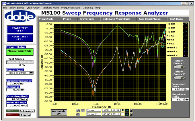
For a delta/wye transformer, a test voltage of variable frequency (normally 20 hertz [Hz] to 2 megahertz [MHz]) is placed across each phase of the high-voltage winding. With this set of tests, low-voltage windings are isolated with no connections on any of the bushings. An additional set of tests is performed by short circuiting all the low-voltage windings and again placing the test voltage on each phase of the high-voltage winding. A third set of tests is made by isolating the high-voltage winding and placing the test voltage across each low-voltage winding. See the M5100 SFRA Instrument Users Guide, Doble Engineering Company for connection details. Picture 1 shows test traces on a new three-phase transformer. The top three traces were taken on the low-voltage side: X1-X3, X2-X1, and X3-X2. The two outside windings (A and C phases) have the same general shape with a “W” at the lowest point of the trace, while the inside winding (B phase) has a “V” at the bottom. The high-voltage traces (lower three) have the same characteristics. Note that, in both high- and low-voltage tests, the traces fall almost perfectly on top of each other for the outside windings (A and C), while the inside winding (B phase), is slightly displaced to the left. These are characteristic traces of a three-phase transformer in good condition. These traces will be the baseline for future tests on this transformer.
Picture 1: SFRA Test Traces of a New Transformer
By comparing future traces with baseline traces, the following can be noted. In general, the traces will change shape and be distorted in the low frequency range (under 5,000 Hz) if there is a core problem. The traces will be distorted and change shape in higher frequencies (above 10,000 Hz) if there is a winding problem. Changes of less than 3 decibels (dB) compared to baseline traces are normal and within tolerances. From 5 Hz to 2 kilohertz (kHz), changes of + or – 3 dB (or more) can indicate shorted turns, open circuit, residual magnetism, or core movement. From 50 Hz to 20 kHz +/- 3 dB (or more), a change from baseline can indicate bulk movement of windings relative to each other. From 500 Hz to 2 MHz, changes of +/- 3 dB (or more) can indicate deformation within a winding. From 25 Hz to 10 MHz, changes of +/- 3 dB (or more) can indicate problems with winding leads and/or test leads placement. The above diagnostics come from the Euro-Doble Client Committee after much testing experience and analysis. Note that there is a great deal of overlap in frequencies, which can mean more than one diagnosis.
Picture 2: SFRA Test Traces of a Defective Transformer
Picture 2 shows traces of a transformer with a problem. This transformer test results are used for illustration only. The traces have the same general positions on the graph as the good transformer. The lower traces are high-voltage winding tests, while the upper traces are the low-voltage winding tests. Note in the higher frequencies of the low-voltage traces that “A” phase (X1-X0 green trace) is displaced from the other two phases more than 3 dB from about 4 kHz to about 50 kHz. With a healthy transformer, these would fall almost on top of each other as the other two phases do. Also notice that “A” phase (H1-H3 Lsh) is displaced in the test with the low-voltage winding shorted. There is an obvious problem with “A” phase on the low-voltage side. After opening the transformer, it was found that the “A” phase winding lead had burned off near the winding connection and re-welded itself on the winding at a different location, effectively shorting out a few turns. The transformer was still working, but hot metal gases (ethylene, ethane, methane) were actively generating and showing up in the DGA. Although other tests could have revealed this problem, SFRA showed the problem was with “A” phase and, therefore, where to concentrate the internal inspection.


No comments:
Post a Comment