As detailed, the necessary EMCS points are entered in the process flow diagram, and the number and function of the individual EMCS points precisely defined. To obtain a PI flow diagram in conformance with the standard (DIN 19227/Part 1), the type, inclusion into the basic structure of the automation system and the functionality (letter code) are to be defined in accordance with steps 1 to 3:
Step 1 – Type of EMCS point
>> Depending on the functional scope of the EMCS point (designation scope of letter code) the following symbols are used:
>> If a process control system is used:
>> If a programmable logic controller is used (PLC technology):
Step 2 – Integration of EMCS point into the basic structure of the automation system
>> If we go back to the basic structure of the automation system, the EMCS point initially determined according to type is to be further modified into:
>> The project designer also defines what the EMCS point will be or which components of the basic structure of the automation system it will cover.
Step 3 – Functional content of EMCS point
>> The functional content of the respective EMCS point is uniquely defined by the letter code; the letter code selected for each EMCS point specifies whether it is to be entered in the process flow diagram as a separate measuring point, closed control loop or binary measuring system.
In accordance with DIN 19227 (Part 1/Sheet 6), the use of the letter code and the design of the PI flow diagram (interpretation of the EMCS point) are explained with the help of the introductory example (Picture 1).
Picture 1: Introductory example demonstrating the letter code in the PI flow diagram (using the example of a temperature measuring point)
Generally, letters are to be used in the following order:
>> Initial letter for typical process technology process parameters:
T – Temperature;
P – Pressure;
F – Flow rate / throughput;
L – Filling level /height and;;
Q – Quality (e. g. pH-value);
>> Second letters for the modification of these process parameters:
D – Difference;
F – Relationship;
J – Measuring point sensing;
>> Subsequent letters (1st subsequent letter/2nd subsequent letter) – for the typical functions for the automation of process technology operations:
C – Closed loop control;
I – Display;
R – Registration;
S – Circuit, sequence control/logic control system;
Y – Arithmetic function;
The EMCS point number which is also defined in the introductory example is introduced dependent on the project and can, for instance, comprise three, four or more characters.
Picture 2: Method of operation of servo controlled equipment (in PI flow diagram)
The practical implementation of the PI flow diagram
The PI flow diagram therefore forms the definitive basis for further realisation of the automation system project with regard to technical engineering. This requires a corresponding project classification, e. g. for the selection of sensors, actuators and processors. Within this context, the selection of sensors and actuators is also designated in the form of field instrumentation and the additionally required second task of configuration in the form of – selection of the process control technology. This enables the task to be subdivided and very often translated into practical team work. This means that, one section of the team prepares the field level instrumentation, and the other section the selection and commissioning of the process control system.
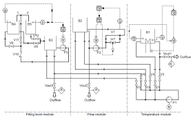
To provide a better understanding, the small-scale trial system is used as an example to introduce the official PI flow diagram in accordance with DIN, followed by the PI flow diagram variant favoured by the Department of Automation. The latter is also within the framework of DIN 19227, but specifies the allocated sensors as additional EMCS point for each closed loop control and binary control system. This creates a central interface, the EMCS points terminal, which provides the field signals for the connection of the process control technology (Picture 3).
Picture 3: PI Flow Diagram
Within the framework of the core project design, the PI flow diagrams are followed by the so-called EMCS block diagrams. In the sense of a level-graded project specification, a preliminary EMCS block diagram and a final EMCS diagram are prepared for each EMCS point, whereby the preliminary EMCS block diagram defines the connection of the automation equipment involved in the configuration of an EMCS point and the final EMCS block diagram documents the detailed wiring based on this. Again, suitable symbols are used when drawing up these EMCS block diagrams to indicate how the so-called standardised signals are used to connect the automation devices deployed.


No comments:
Post a Comment