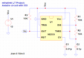
The astable circuit with timer 555 is shown on Picture 1. In order to avoid the unwanted modulation during the controlling, the controlling pin of the circuit (CV-pin) is grounded via the capacitor C1 of 10 nF. The astable mode of work can be stopped with connecting the RST (reset) pin on low potential, and then, in order to reestablish the astable mode, the RST pin should be connected on high potential again.
Picture 1: Astable circuit with integrated 555 timer
Time-domain analysis
The results of the transient analysis for this circuit in time domain is shown on Picture 2. The output of the circuit is on its low level of about 7 mV, and the output high level of about 12 V. The first output pulse starts at about 1.1 ms and ends at about 2.5 ms, so the time duration of the output pulses is about 1.4 ms. The pause between the output pulses, when the output signal is at its low level, is about 0.7 ms.
Picture 2: Transient analysis - output voltage Vo wave form (time-domain)


No comments:
Post a Comment